

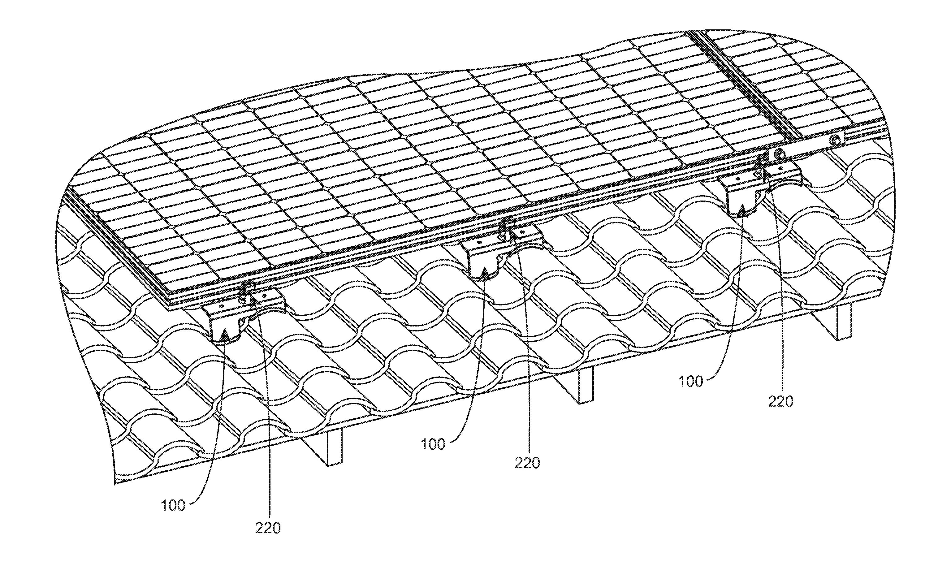
Integrated hook and flashing for photovoltaic module installation on tile roofs
a photovoltaic module and tile roof technology, applied in the direction of heat collector mounting/support, machine supports, light and heating equipment, etc., can solve the problems of brittleness, rigid tiles, and inability to simply drill/need/screw through, and achieve the effect of increasing the cost of manufacturing and potentially far more time-consuming
- Summary
- Abstract
- Description
- Claims
- Application Information
AI Technical Summary
Benefits of technology
Problems solved by technology
Method used
Image

Examples
Embodiment Construction
[0033]The following description is intended to convey a thorough understanding of the embodiments described by providing a number of specific embodiments and details involving PV mounting hardware for sloped tile roofs. It should be appreciated, however, that the present invention is not limited to these specific embodiments and details, which are exemplary only. It is further understood that one possessing ordinary skill in the art, in light of known systems and methods, would appreciate the use of the invention for its intended purposes and benefits in any number of alternative embodiments, depending upon specific design and other needs.
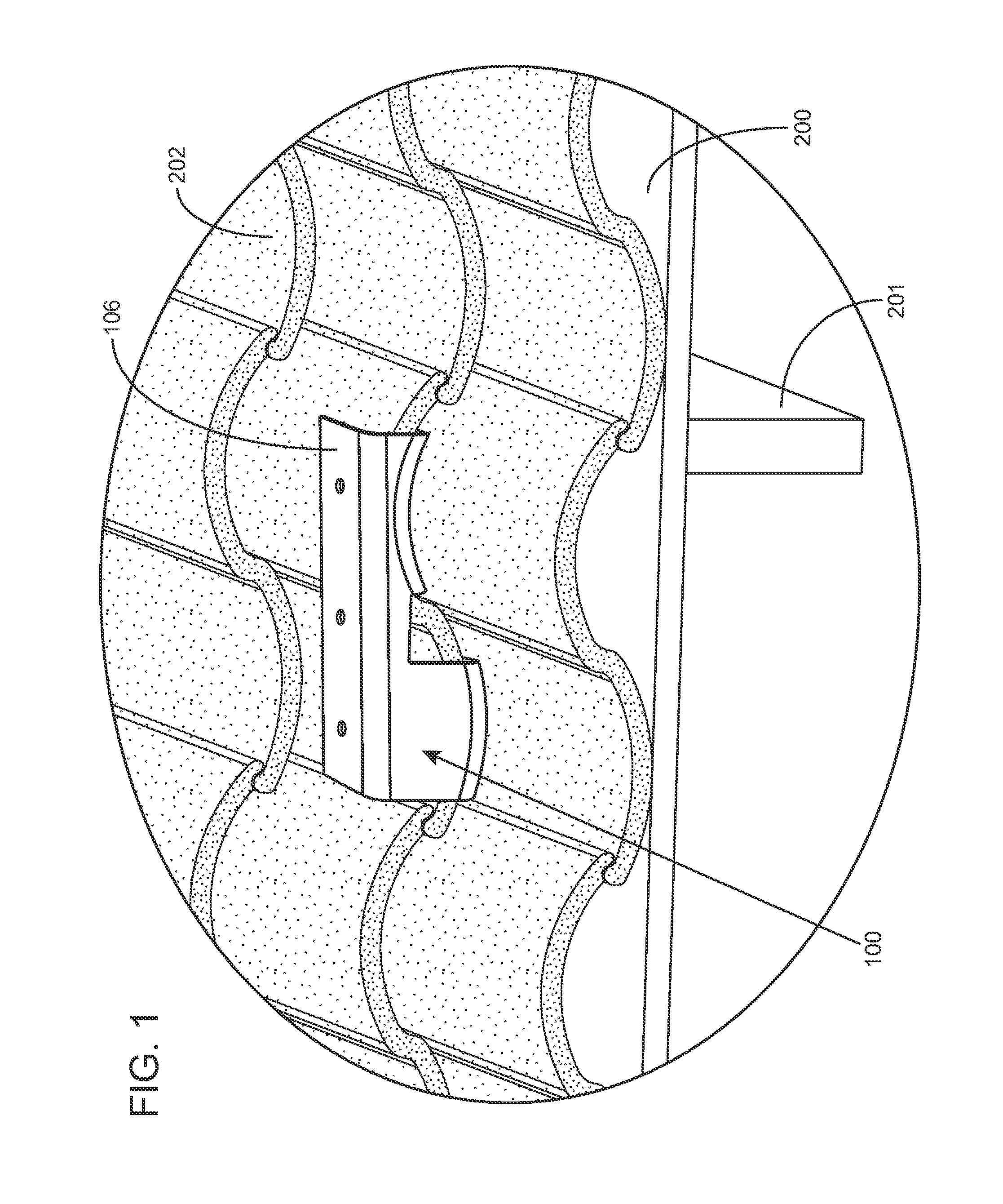
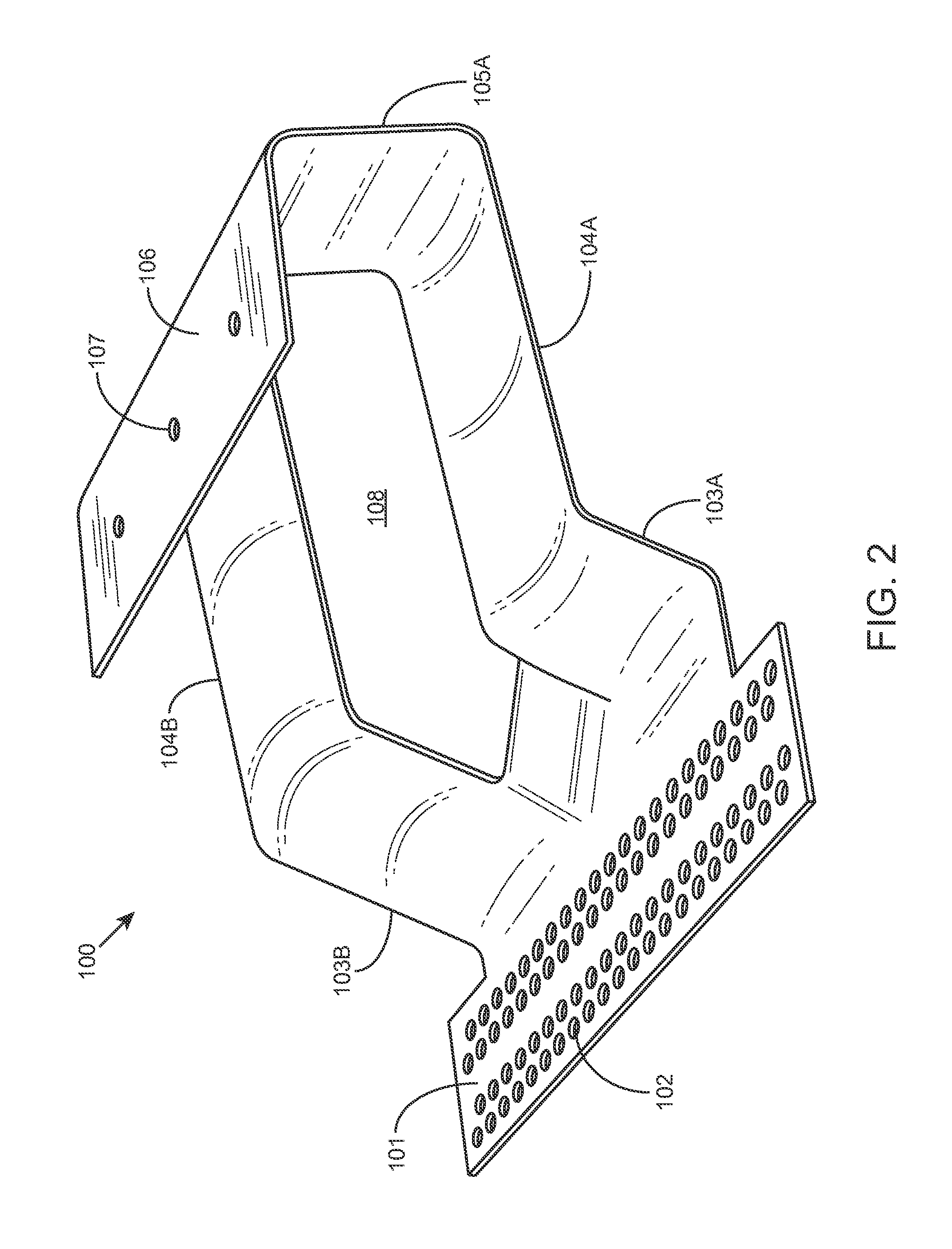
[0034]FIG. 1 illustrates exemplary hook and flashing bracket 100 for photovoltaic module installation on tile roofs according to various embodiments of the invention. Bracket 100 can be a rigid assembly formed from steel, aluminum, or other rigid, corrosion resistant material. In some embodiments, bracket 100 may be press formed from a sheet of mat...
PUM
 Abstract
Description
Claims
Application Information