Massage apparatus

Inactive Publication Date: 2016-04-21
TOYOTA BOSHOKU KK
View PDF1 Cites 38 Cited by
  • Summary
  • Abstract
  • Description
  • Claims
  • Application Information

AI Technical Summary

Benefits of technology

[0016]According to the above structure, the projection of the cam is formed so as to have the inclined surface at the front end portion. As a result, an abutting force generated when the projection and the limit switch

Problems solved by technology

Thus, a circuit that actuates the counter upon receiving a signal from the optical sensor is required, s

Method used


Image

  • Massage apparatus
  • Massage apparatus
  • Massage apparatus

Examples


Embodiment Construction

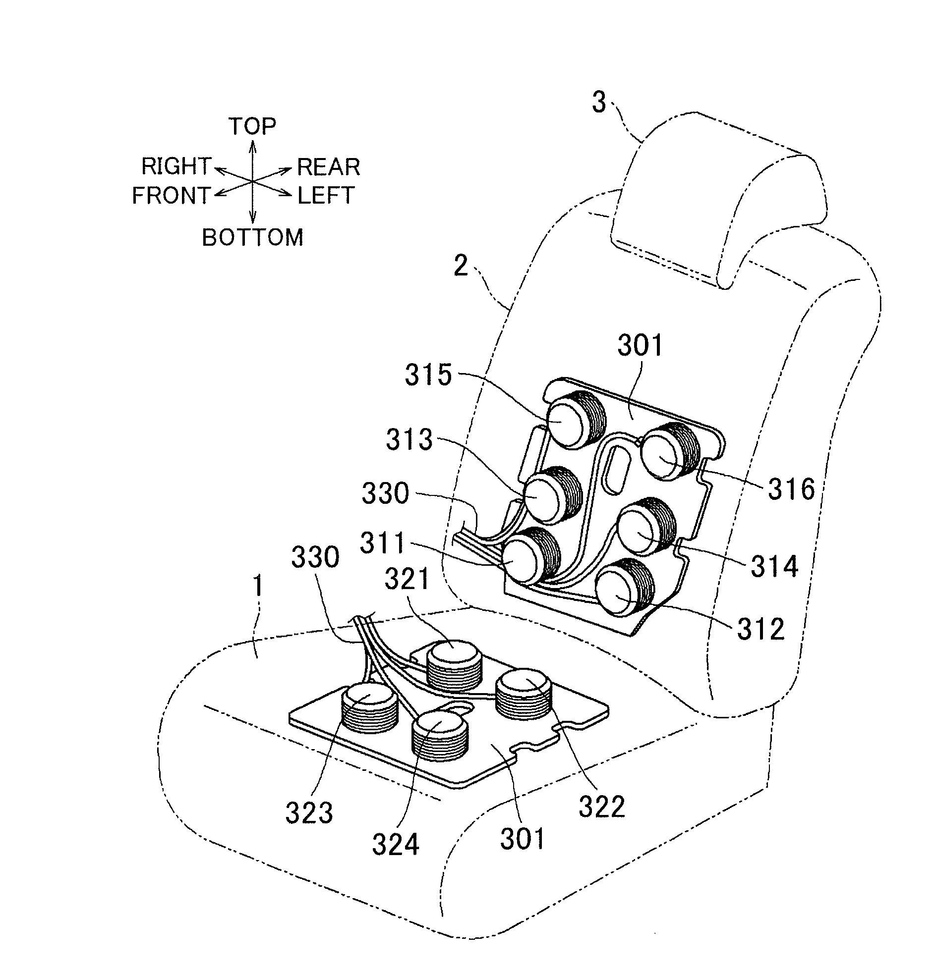
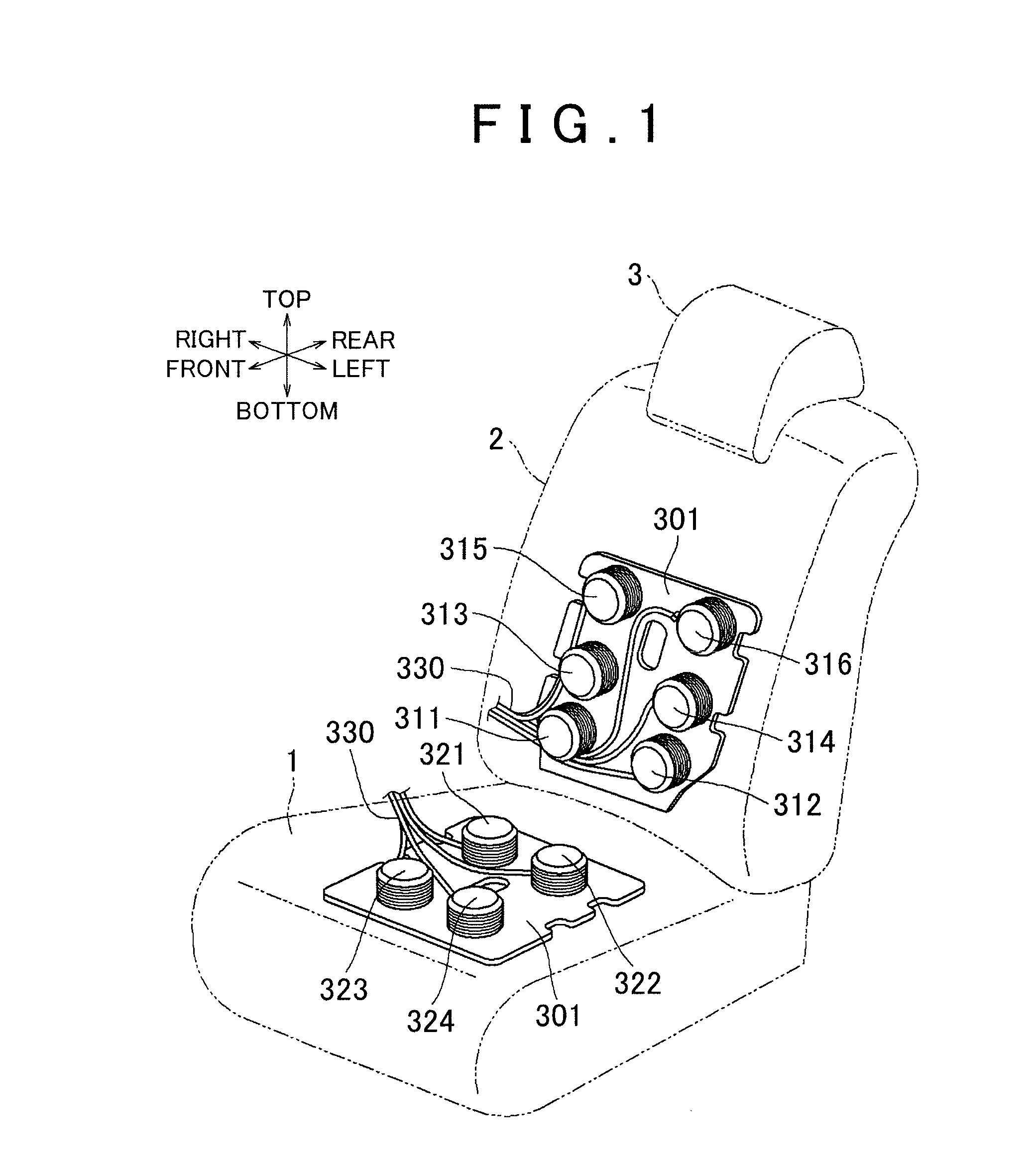
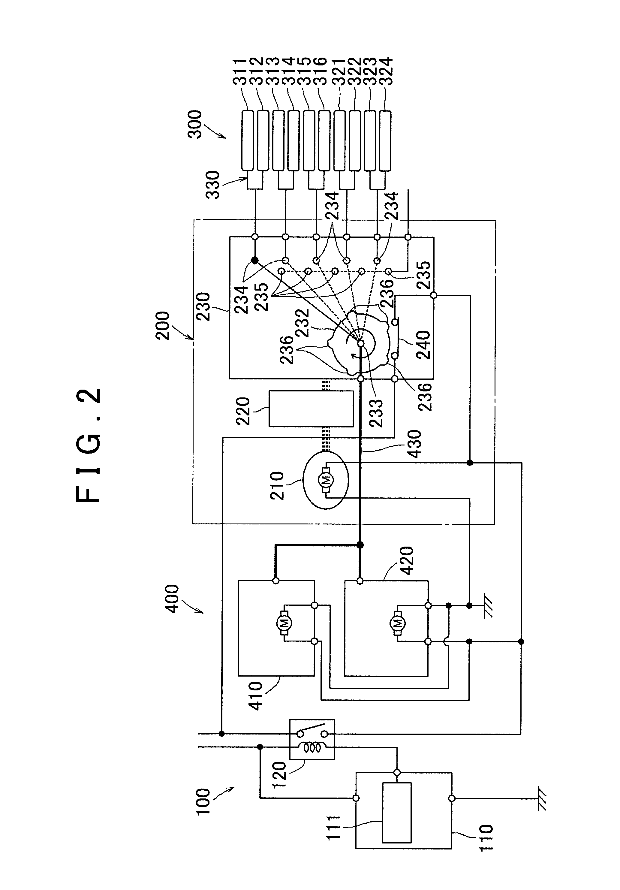
[0030]FIGS. 1 to 12 show one embodiment of the invention. The embodiment shows an example in which a massage apparatus according to the invention is applied to an vehicle seat (hereinafter referred to simply as a seat). The massage apparatus includes a plurality of bladders 311 to 316, 321 to 324 that are disposed along a seating surface of a seatback 2 constituting a backrest and a seating surface of a seat cushion 1 constituting a seat portion in the seat, respectively. A headrest 3 that supports a head portion of an occupant from behind is also provided on an upper portion of the seatback 2.

[0031]Here, the bladders 321 to 324 on the seat cushion 1-side are bilaterally paired into two pairs, and the two pairs are respectively arranged on a front side and a rear side of the seat. The bladders 311 to 316 on the seatback 2-side are bilaterally paired into three pairs, and the three pairs are vertically arranged. The bladders 311 to 316 are fixed onto a bladder base 301 that is fixed ...


PUM


Abstract

A massage apparatus includes: a pump that is an air supply source; a motor that actuates a distributor; a power switch that optionally supplies power to the pump and the motor to actuate the pump and the motor; and a limit switch that is connected in parallel with the power switch, and is operated by a cam working with the distributor so as to be turned ON when the distributor assumes a position to supply air to any of bladders, and so as to be turned OFF when the distributor assumes a position to discharge air from at least any of the bladders.

Description

INCORPORATION BY REFERENCE[0001]The disclosure of Japanese Patent Application No. 2014-212299 filed on Oct. 17, 2014 including the specification, drawings and abstract is incorporated herein by reference in its entirety.BACKGROUND OF THE INVENTION[0002]1. Field of the Invention[0003]The invention relates to a massage apparatus that performs a desired massage by supplying and discharging air to and from a bladder provided in the apparatus of a seat or the like.[0004]2. Description of Related Art[0005]In an air mat apparatus disclosed in Japanese Patent Application Publication No. 9-38153, a plurality of bladders are arranged in a planar manner to constitute an air mat. The bladders are divided into a plurality of groups, and air is alternately supplied to and discharged from the bladders in the respective groups, so that a body of a person lying on the air mat is massaged.[0006]With similar uses as the above air mat apparatus, a massage seat for a vehicle is developed. The massage se...

Claims


Application Information

Patent Timeline
IPC IPC(8): A61H9/00B60N2/90
CPCA61H2201/1215A61H9/0078A61H2201/0149A61H2201/0169B60N2/976A61H2201/1654A61H2201/5002A61H2201/5066
Inventor UNO, YOSUKESAITO, KOJIYANAGAWA, MASASHIONUMA, MASAHIKO
Owner TOYOTA BOSHOKU KK
Why Eureka
Try Eureka