Improvements in and relating to splitting apparatus

a technology of splitting apparatus and a splitter, which is applied in the field of splitting apparatus improvement and relating to the splitter, can solve the problems of high risk of misplacing the blow, high risk of injury to the person, dangerous use of the tool, etc., and achieves the effects of less abrasion, less force, and cost-effective and durabl

Active Publication Date: 2016-04-21
HUTCHINSON VAUGHAN JOHN
View PDF48 Cites 22 Cited by
  • Summary
  • Abstract
  • Description
  • Claims
  • Application Information

AI Technical Summary

Benefits of technology

[0052]The benefits are that there are no requirements to apply so much force via the present invention as the user is not driving the cutting means into the wood from above. It only requires a mallet, which reduces the weight to be handled and of the need for as much force by the user.
[0160]Having regard to the above description, it should be appreciated that the splitting apparatus provides a means for splitting / cutting up materials in a way that can provide potentially realisable advantages, in so far as, the apparatus is adapted to be, or is able to be adapted to be:

Problems solved by technology

The problems with axes, mauls and tomahawks are that such tools are dangerous to use, particularly if used by inexperienced people.
There is a high risk of misplacing the blow.
A misplaced blow or an over-swing of the tool may result in the axe / maul head hitting the person instead of the wood, resulting in direct injury to the person and potentially resulting in loss of life and / or limbs.
In addition, the impact of the axe / maul head against the wood may cause the head to bounce off the wood via a ricochet or recoil action, which could injure the user.
The head may become imbedded in the wood and the moisture and suction created may make the head hard to extricate from the wood.
This increases the danger of wood moving in any direction at considerable speed which can cause injury.
Also, the physical force required can again be either unachievable for someone not strong enough or cause injury due to the strain required to create enough force to split the wood.
Further, motor or electric driven pneumatic / hydraulic splitters are large bulky machines and are not generally affordable for many people.
They are not suitable for daily use due to their size and cost.
Such machines also consist of many moving parts that can break down and require maintenance, which increases the cost of operation.
In addition, the risk of injury is greater due to the power the motorised parts produce and operate at.
The pressure applied may fracture the material, but the material may fly out from the point of impact.
In addition, too much pressure can crush the material into very fine fragments and too little can result in large chunks.

Method used


Image

  • Improvements in and relating to splitting apparatus
  • Improvements in and relating to splitting apparatus
  • Improvements in and relating to splitting apparatus

Examples


example 1

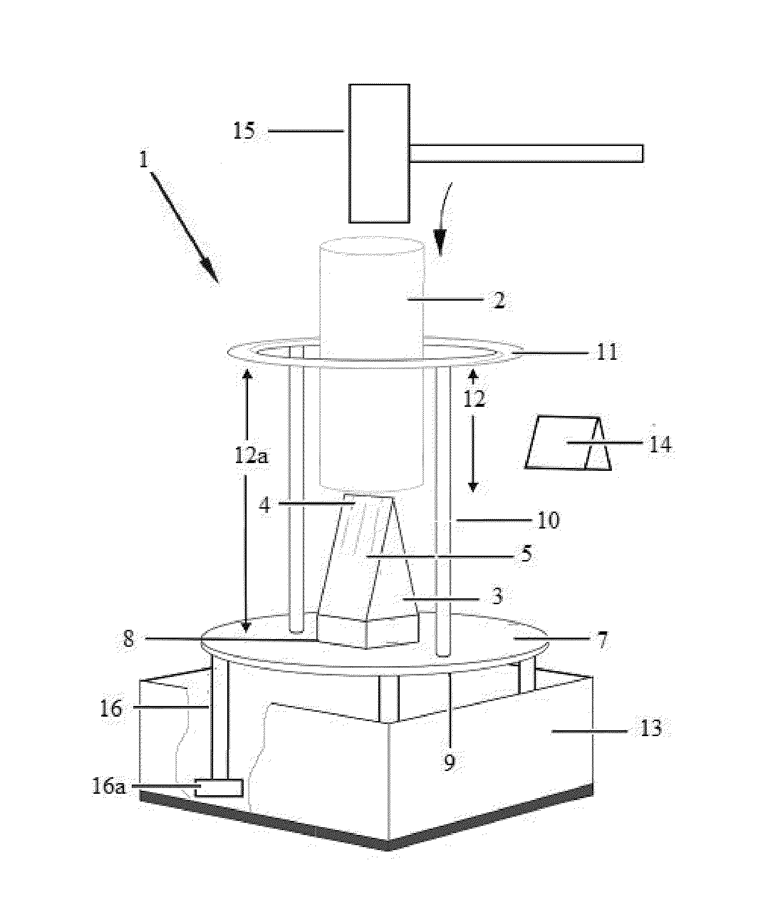
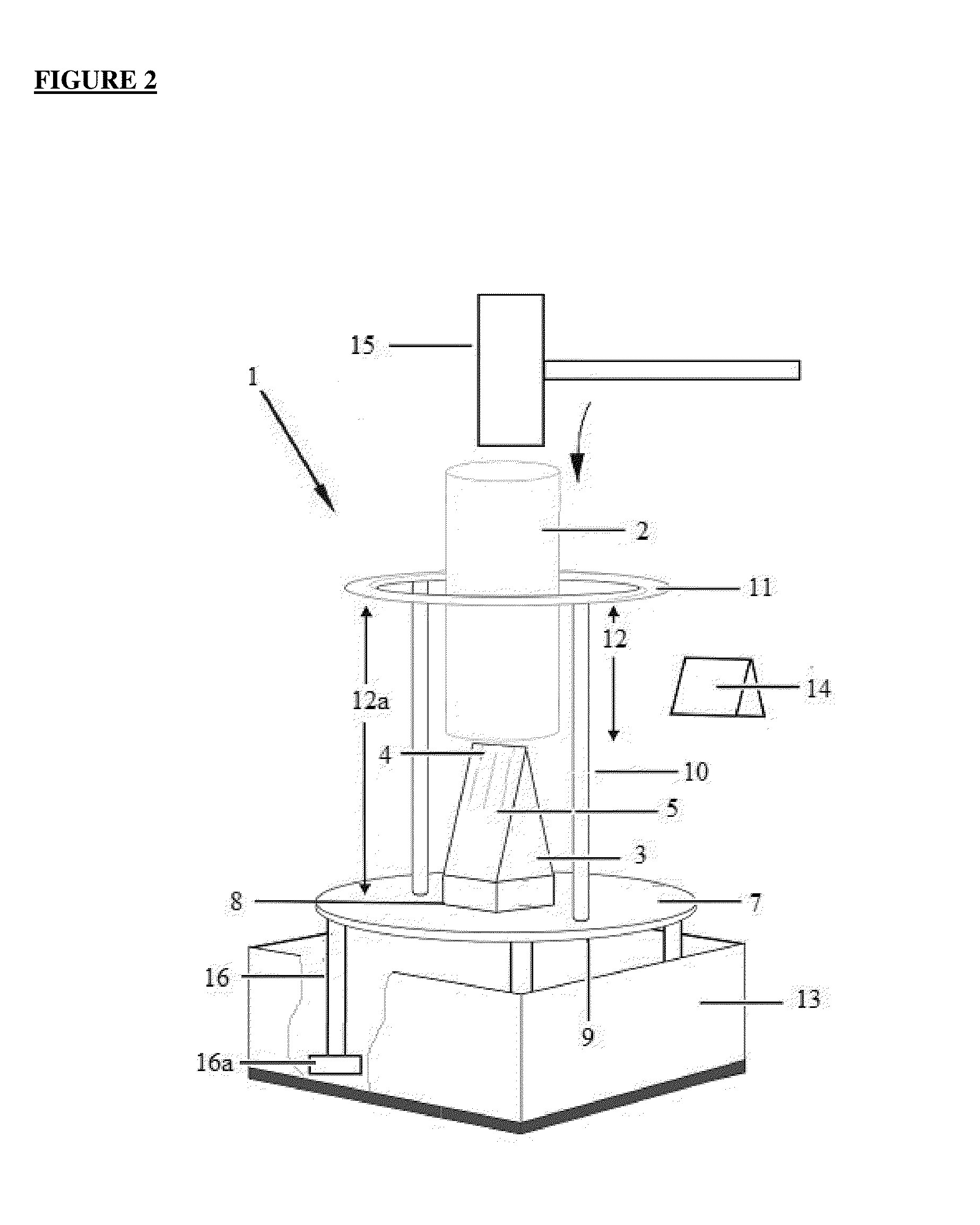
[0219]Method of assembling the splitting apparatus in one embodiment is achieved by the following steps:[0220]a) From a substantially flat piece of the constructional material, cut out the body / base to a desired shape, size and thickness; and[0221]b) Determine the cutting means to be used; and[0222]c) Attach the cutting means to the centre of body; and[0223]d) Cut supporting means to a desired length and attach relative to the base;[0224]e) Prepare the safety means to a preferred size and shape to complement the base, or as may be required to accommodate the material to be split within a central aperture provided in the safety means; and[0225]f) Position the safety means relative to the upper distal ends of the supporting means and secure in one or more locations; and[0226]g) Engage optional stabilising means as required.

[0227]It is to be noted the stabilising means may be an extension of the length of the supporting means that extend beyond the base / body.

[0228]An alternative assemb...

example 2

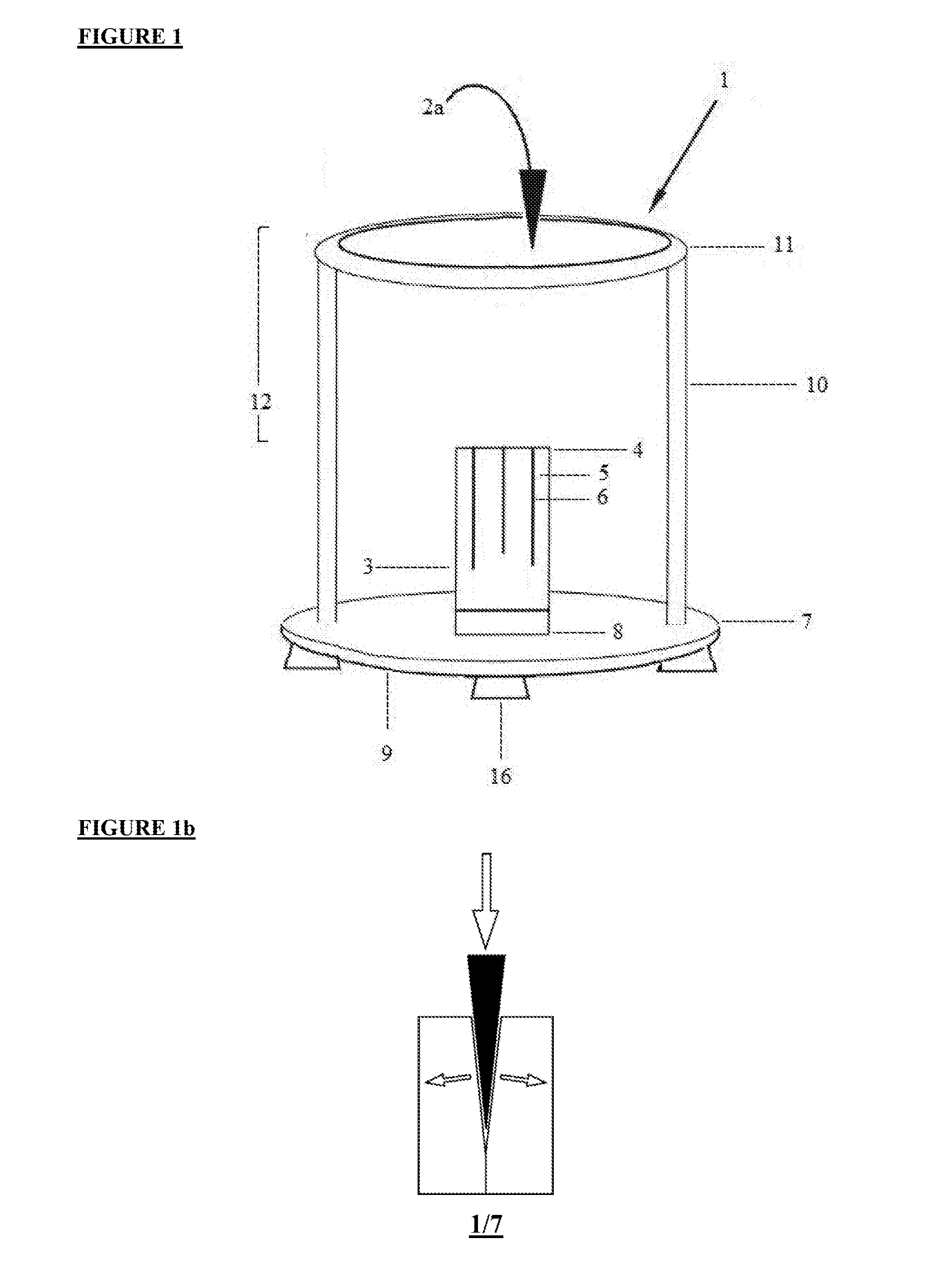
[0237]In using the splitting apparatus, the following steps are followed:[0238]a) Stabilise the splitting apparatus against a surface on which it is to be used; and[0239]b) Place material you wish to split (in this case wood) down through the centre of the safety means (as shown at 2a in FIG. 1) until it rests on top of the cutting means; and[0240]c) Support the material, if required, with one hand so that it is in a substantially vertical arrangement and sits on top of the cutting means (which would be substantially centred on the base and in turn centered with respect to the safety means); and[0241]d) Holding pressure means in the other hand, tap gently but firmly on to the top of the material forcing the material downwards on to the cutting means, until the material splits (using as much force as may be required)

[0242]It is to be noted the process may be repeated several times to further split the pieces of material obtained from previous splitting actions, until they reach the d...


PUM

PropertyMeasurementUnit
diameteraaaaaaaaaa
diameteraaaaaaaaaa
thickaaaaaaaaaa

Abstract

Disclosed is an apparatus for mechanically splitting materials, including a body with a cutting element arranged relative thereto. The cutting element includes at least one cutting surface oriented vertically. The splitting apparatus includes the cutting element applying an upward pressure against the material which is split when a separate downward force is applied to the material. The body of the splitting apparatus also includes a safety element to protect the user from the cutting element; an elongate supporting element to distance the safety element from either or both the cutting element and a surface on which the splitting apparatus is used; a stabilizing element to stabilize the splitting apparatus relative to a surface on which the splitting apparatus is used; and optionally a deflecting element to deflect split materials away from the cutting element and container element to contain therewithin split materials produced during the splitting.

Description

TECHNICAL FIELD[0001]This invention relates to improvements in and relating to apparatus for mechanically splitting materials and to the method of manufacturing and using the apparatus.[0002]Particularly, the invention relates to a means for splitting wood to produce kindling. The apparatus enables wood to be split with substantially reduced force. The apparatus and method of using the apparatus substantially improves the ability to safely and effectively split the wood.[0003]It is envisaged the invention will be applicable to any situation, for example agricultural, horticultural, forestry, commercial, industrial or domestic situations where material is required to be split to smaller pieces.[0004]However, while the present description relates primarily to splitting wood to produce kindling for use in establishing a fire, the invention may have applications outside this field and the apparatus may be adapted for splitting materials for other purposes. For example, a food quality ve...

Claims


Application Information

Patent Timeline
Patent Type & Authority Applications(United States)
IPC IPC(8): B27L7/08B27G21/00B27L7/06B26D7/22
CPCB27L7/08B27L7/06B27G21/00B26D7/22B26D1/02B27L7/00
Inventor HUTCHINSON, AYLAHUTCHINSON, VAUGHAN JOHN
Owner HUTCHINSON VAUGHAN JOHN
Why Eureka
Try Eureka