
Controlled flight of a multicopter experiencing a failure affecting an effector

a multi-copter and effector technology, applied in vehicle position/course/altitude control, process and machine control, instruments, etc., can solve the problems of inability to guarantee safe and efficient control in many real-world operating conditions, limited cost-effectiveness, and the need for human pilots, so as to reduce the limitations of previous methods for controlling multi-copters.

Active Publication Date: 2016-04-21
ETH ZZURICH
View PDF0 Cites 75 Cited by
  • Summary
  • Abstract
  • Description
  • Claims
  • Application Information

AI Technical Summary

Benefits of technology

The present invention offers a better way to control multicopters, which can be designed with fewer effectors and have more efficient systems. This can reduce risks and increase safety and reliability. Additionally, it can simplify the design of existing multicopters and improve their performance.

Problems solved by technology

The need for human pilots severely limits the cost-effectiveness, possible operating conditions, and flight endurance of multicopters in many applications.
For example, even experienced human pilots cannot guarantee safe and efficient control in many real-world operating conditions including wind and turbulence.

Method used


Image

  • Controlled flight of a multicopter experiencing a failure affecting an effector
  • Controlled flight of a multicopter experiencing a failure affecting an effector
  • Controlled flight of a multicopter experiencing a failure affecting an effector

Examples


Embodiment Construction

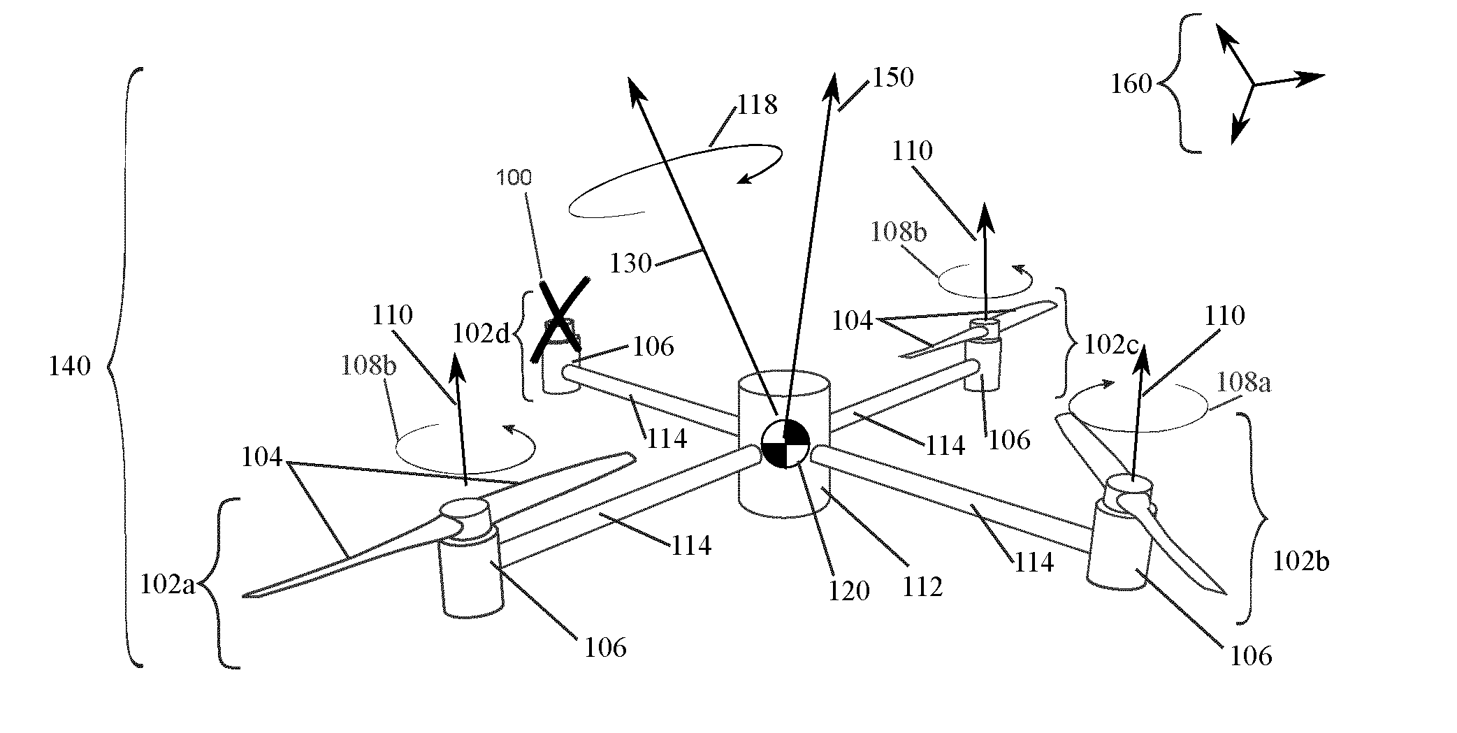
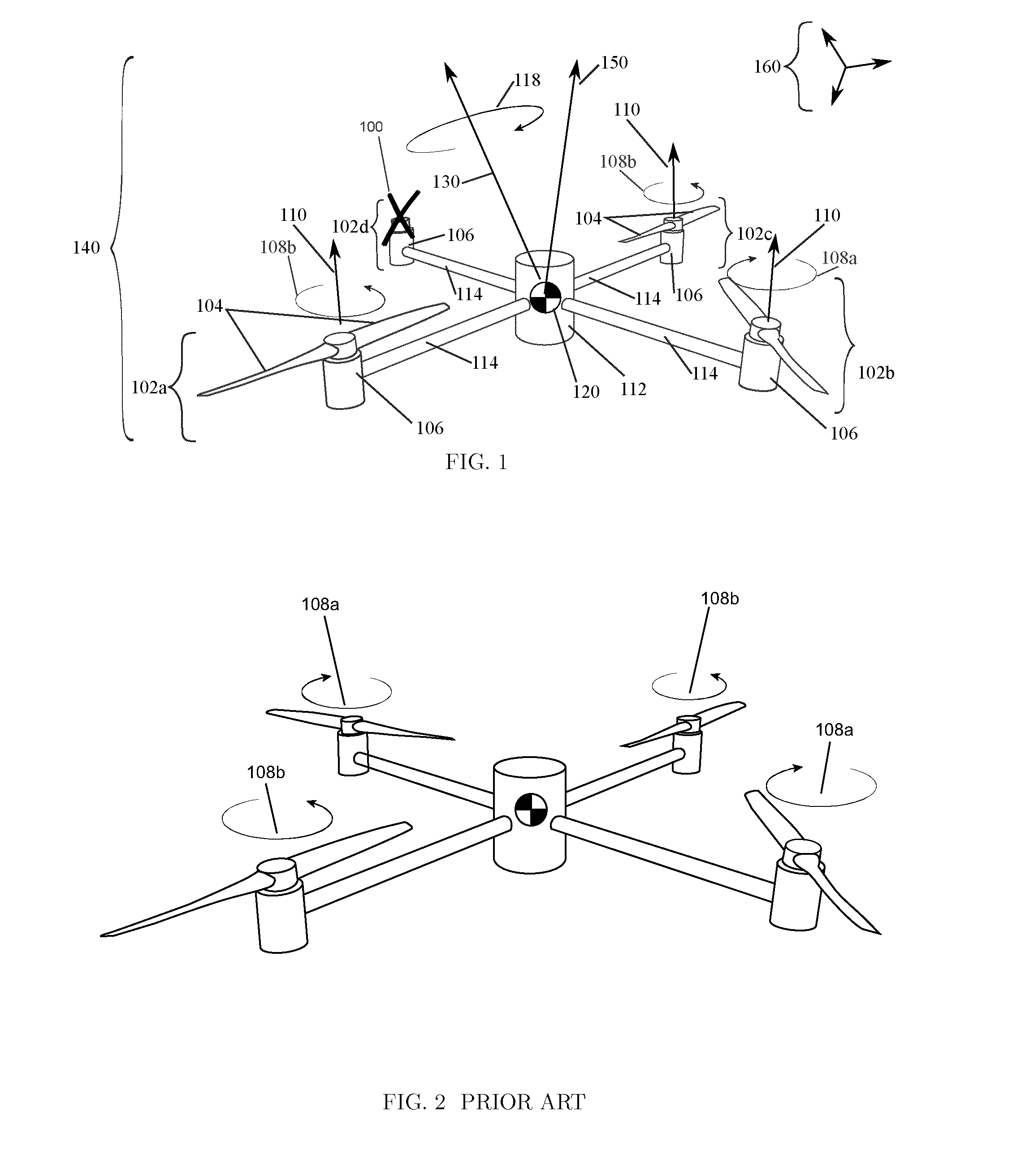
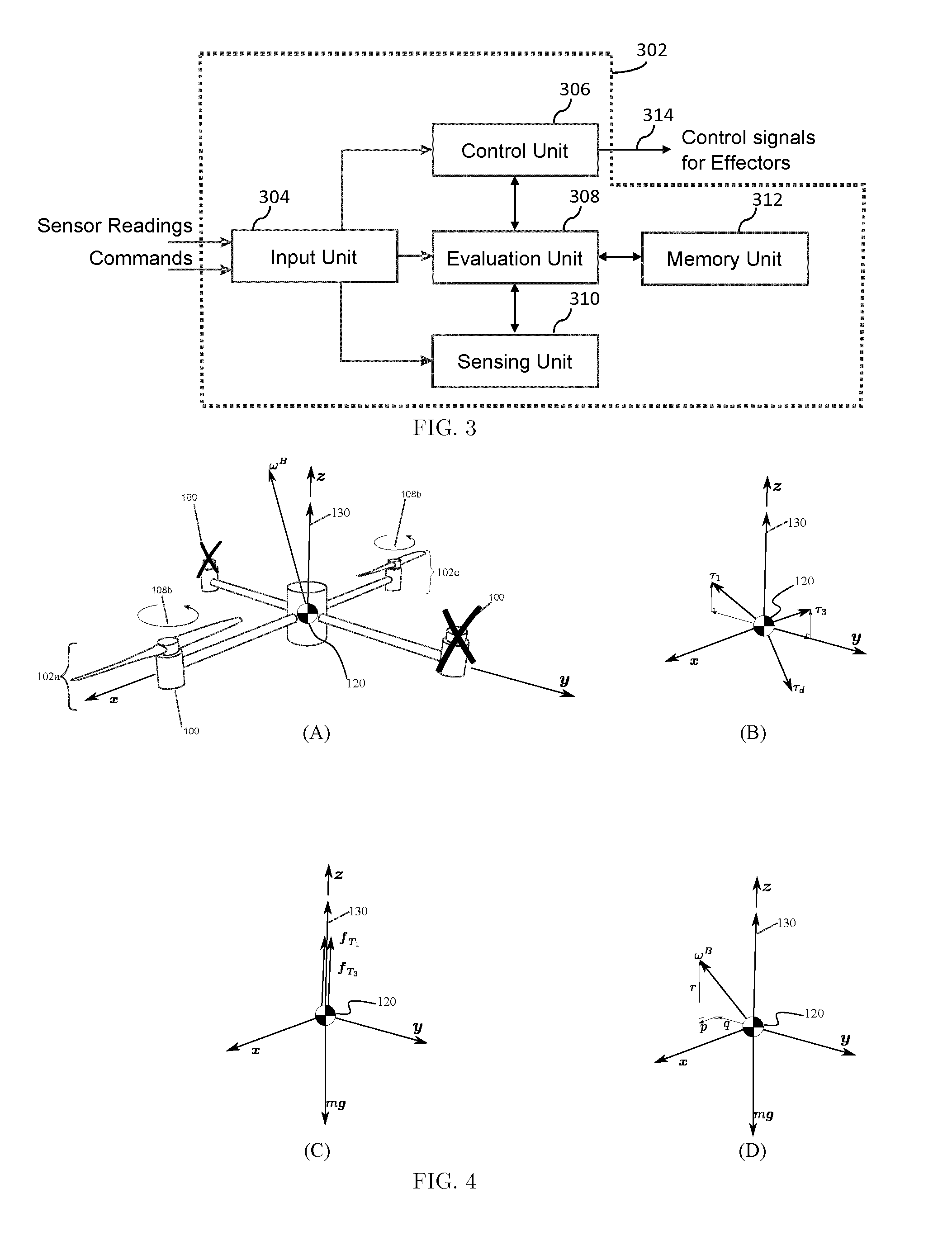
[0138]The disclosed invention relates to the control of motion of a multicopter experiencing a failure affecting one or more effectors. Multicopters are typically equipped with effectors that produce both a thrust force and a torque acting on the multicopter. These effectors are typically characterized by having a characteristic drive axis (typically identical to the direction of thrust force), which is fixed with respect to the body of the multicopter, and by having a single variable which controls the thrust force. For example, the fixed-pitch propellers used on many hover-capable aerial vehicles such as multicopters produce a thrust force and torque acting on the vehicle, and are typically directly fixed to a motor's fixed drive axis and commanded using a single variable. For multicopters, this single variable typically commands the relative desired speed of the motor and thus the thrust force of the effector. Multicopters typically use brushless motors, which typically use a mot...


PUM


Abstract

According to a first aspect of the invention, there is provided a method for operating a multicopter experiencing a failure during flight, the multicopter comprising a body, and at least four effectors attached to the body, each operable to produce both a torque and a thrust force which can cause the multicopter to fly when not experiencing said failure. The method may comprise the step of identifying a failure wherein the failure affects the torque and / or thrust force produced by an effector, and in response to identifying a failure carrying out the following steps, (1) computing an estimate of the orientation of a primary axis of said body with respect to a predefined reference frame, wherein said primary axis is an axis about which said multicopter rotates when flying, (2) computing an estimate of the angular velocity of said multicopter, (3) controlling one or more of said at least four effectors based on said estimate of the orientation of the primary axis of said body with respect to said predefined reference frame and said estimate of the angular velocity of the multicopter. The step of controlling one or more of said at least four effectors may be performed such that (a) said one or more effectors collectively produce a torque along said primary axis and a torque perpendicular to said primary axis, wherein (i) the torque along said primary axis causes said multicopter to rotate about said primary axis, and (ii) the torque perpendicular to said primary axis causes said multicopter to move such that the orientation of said primary axis converges to a target orientation with respect to said predefined reference frame, and (b) such that said one or more effectors individually produce a thrust force along said primary axis.

Description

FIELD OF THE INVENTION[0001]The present invention relates to the control of a multicopter experiencing a failure affecting an effector. In particular, the invention relates to a novel scheme for controlled flight that enables translational motion control of a multicopter by causing it to rotate and applying a novel control method, allowing the invention to be used as a failsafe control mechanism in case of effector failure in conventional hover-capable aerial vehicles equipped with multiple rigidly-attached fixed-pitch propellers (“multicopters”).BRIEF SUMMARY[0002]In accordance with the present invention, limitations of previous methods for the control of multicopters have been substantially reduced or eliminated. In particular, it provides a flying vehicle control scheme for vehicles with as few as one functioning effector. In addition, it provides improved systems and methods for the control of flying vehicles in case of a failure affecting one or more effectors.[0003]Technical a...

Claims


Application Information

Patent Timeline
IPC IPC(8): B64C39/02B64D45/00B64C27/08
CPCB64C39/024B64C27/08B64C2201/141B64C2201/024B64C2201/108B64D45/00G05D1/0072B64U2201/10B64U2201/20B64U2101/30B64U50/19B64U40/10B64C27/20B64U10/10B64U10/13B64U30/20B64C13/24B64C27/32B64C2203/00
Inventor D'ANDREA, RAFFAELLOLUPASHIN, SERGEIMUELLER, MARK W.WAIBEL, MARKUS
Owner ETH ZZURICH
Learn More