Ball-lock punch retainer inserts

a technology of retainer and ball lock, which is applied in the field of retainers, can solve the problems of not being able to control the tolerances as needed to make the product function properly, users and customers, die shops, etc., and achieves the effect of speeding up the process of moving the punch hole location, facilitating production, and simplifying the manufacture of the insert holder

Inactive Publication Date: 2007-05-10
MOELLERING DAVID J
View PDF0 Cites 9 Cited by
  • Summary
  • Abstract
  • Description
  • Claims
  • Application Information

AI Technical Summary

Benefits of technology

[0008] The new insert designs also simplify the manufacture of the insert holder, allowing users the option to manufacture their own holder. The insert holder may be a simple block of low alloy steel with tapered or counterbored oblong or teardrop holes, which can easily be produced by wire electro-discharge machining (EDM) or computer numerically controlled (CNC) milling processes. The new insert designs have the benefit of speeding the process of moving a punch hole location, which often happens during die and holder construction. By simply using EDM or CNC machinery for a tapered or counterbored oblong or teardrop hole in a new location, a new punch location is established and the obsolete hole is abandoned. The machining can be done even if the holder or retainer is in a hardened condition.
[0009] The new insert design incorporates the Moeller patented one-piece punch h

Problems solved by technology

Unfortunately, such users cannot generally control the tolerances needed to make the punch retainers function properly.
Use

Method used


Image

  • Ball-lock punch retainer inserts
  • Ball-lock punch retainer inserts
  • Ball-lock punch retainer inserts

Examples


Embodiment Construction

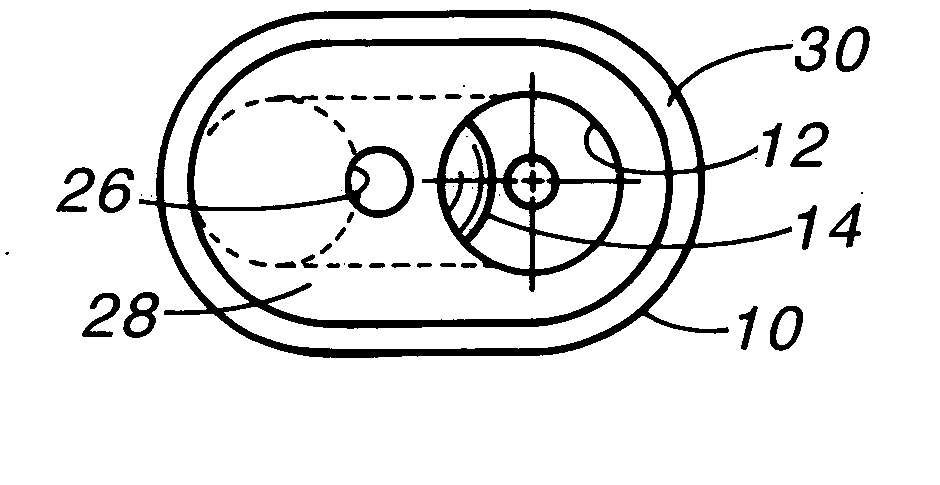
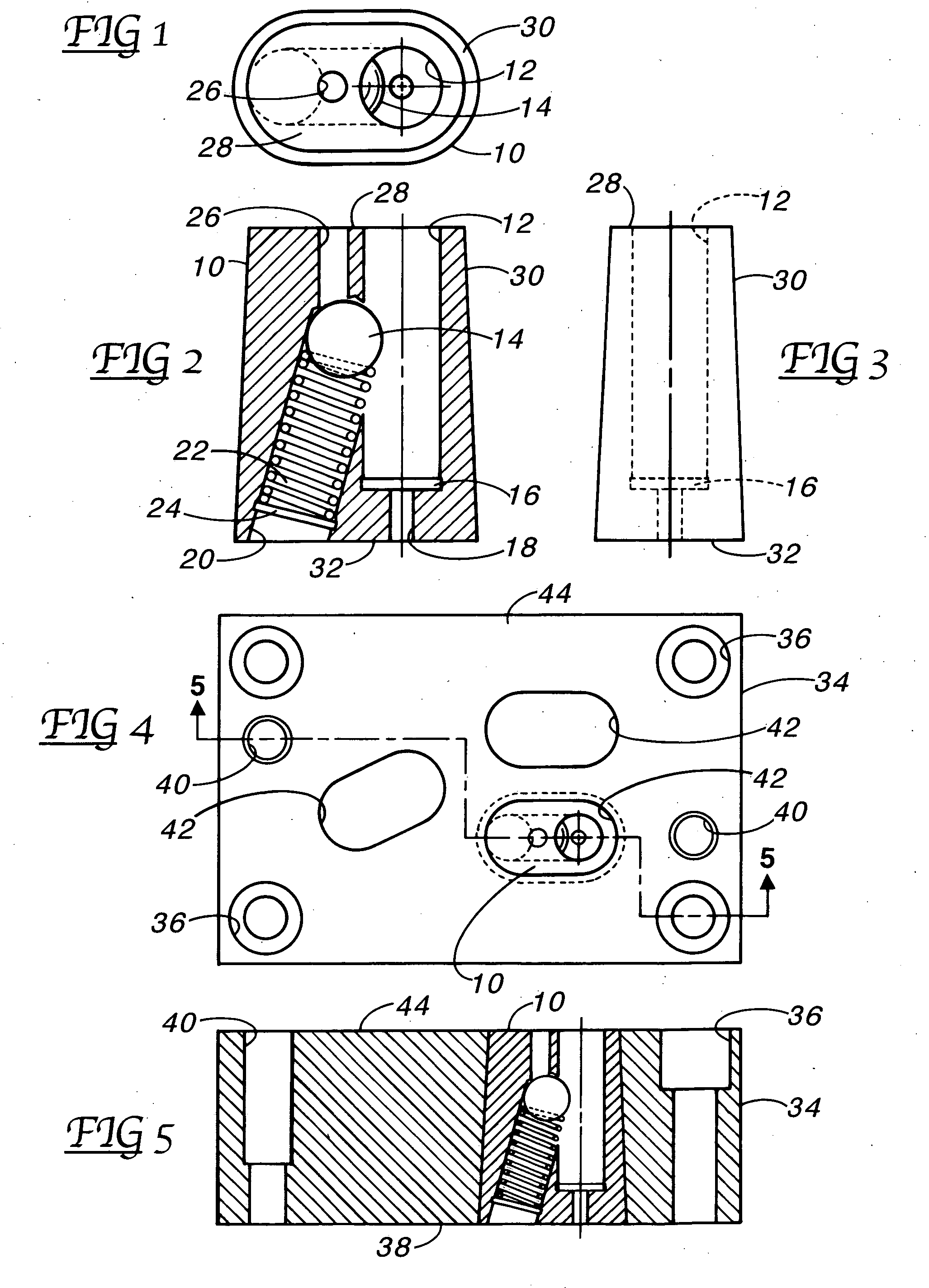
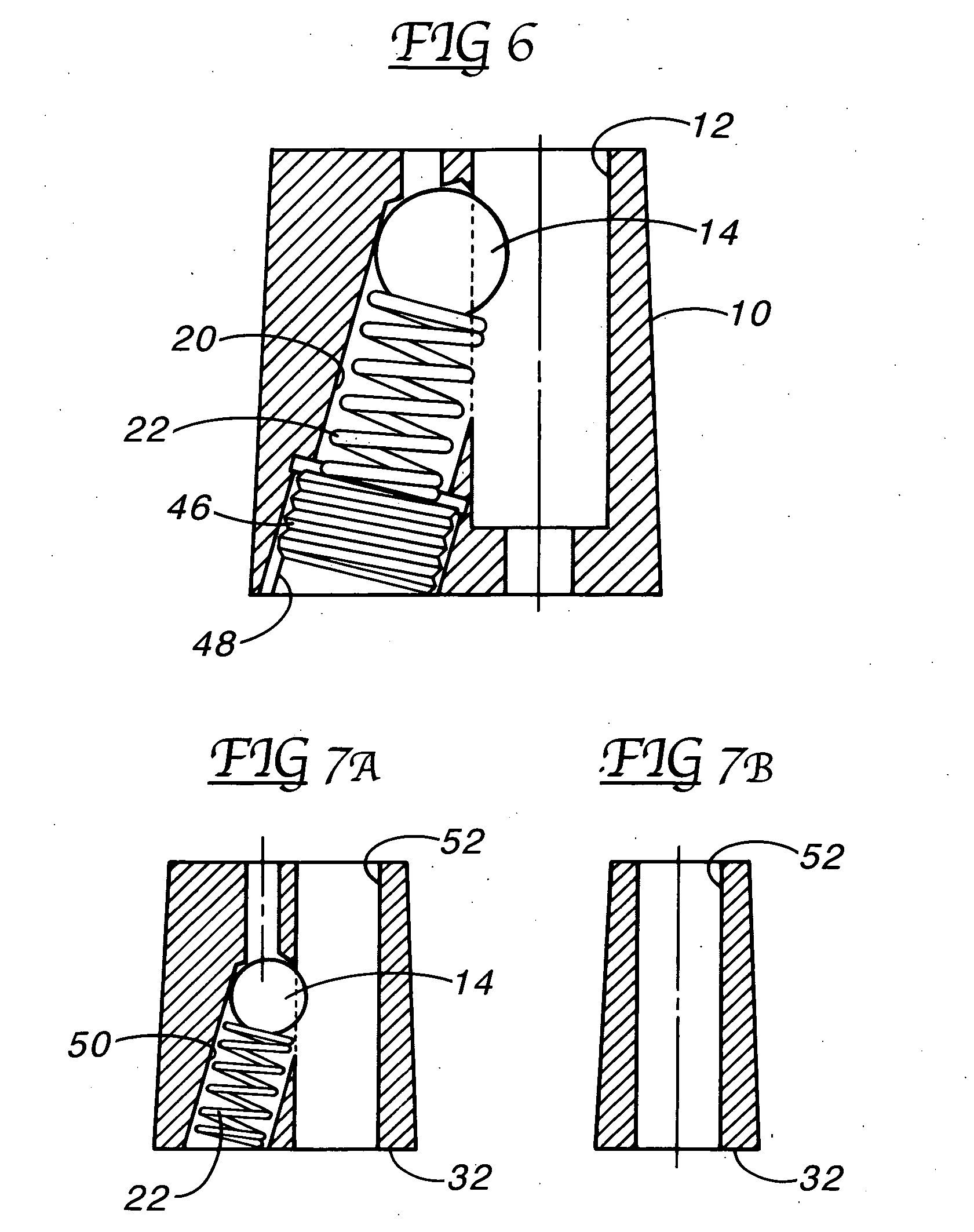
[0029] Illustrated in FIGS. 1, 2 and 3, the new oblong insert 10 has a punch hole or socket 12 and a ball detent 14 partially extending into the socket. The base of the socket 12 includes a counterbore 16 and dowel pin hole 18. An angle hole 20 encloses the ball detent 14, spring 22, and at the end of the spring remote from the ball a counterbore 24 for a snap ring (not shown) is provided. A relief hole 26 extends from the ball detent 14 to the top 28 of the insert 10. The sidewall 30 of the insert body is tapered about the entire insert 10 to provide a larger bottom 32 than top 30.

[0030] In FIGS. 4 and 5, a block retainer or holder 34 is of generally rectangular shape and formed with several bolt holes 36 for attachment of the bottom 38 in contact with a press platen (not shown). Also formed in the block34 are dowel pin holes 40. Typically, the bolt holes 36 and dowel pin holes 40 are formed prior to heat treating of the block 34 and then finished for accuracy, if necessary, when ...


PUM


Abstract

A ball-lock punch retainer insert comprises a tapered oblong or teardrop shape or an enlarged headed shape that completely encloses the punch hole or socket and the angle hole ball detent mechanism. The insert fits in a tapered oblong or teardrop hole or a counterbored hole formed in a block, the block in turn fastenable to a press platen. Tapered oblong or teardrop holes or counterbored holes can be easily formed in a hardened steel block as needed for immediate use. The ball-lock punch inserts can be inventoried for use as needed, thus, the combination provides for quick punch tooling and quick changes by forming new tapered oblong or teardrop holes or counterbored holes in the block.

Description

[0001] This application claims the benefit of provisional patent application Nos. 60 / 736,070 and 60 / 830,632 filed Nov. 10, 2005 and Jul. 13, 2006, respectively.BACKGROUND OF THE INVENTION [0002] The field of the invention pertains to retainers for industrial punches and, in particular, to ball-lock punch retainers. Ball-lock punch retainers utilize an offset ball detent and spring mechanism next to the punch socket in the retainer. [0003] Examples of such retainers are the Accu-Lock™ special retainer inserts from Wilson Tool International, of White Bear Lake, Minn., and the True-Set® retainer from Moeller Manufacturing Co., of Plymouth, Mich. (U.S. Pat. Nos. 5,337,835, 5,410,932 and Des. 351,395). [0004] With a view to providing a more versatile ball lock retainer for special purposes, the following retainer inserts have been developed. SUMMARY OF THE INVENTION [0005] Die shops have begun using rectangular block punch retainers and re-drilling punch sockets as punch locations are ch...

Claims


Application Information

Patent Timeline
IPC IPC(8): B26D7/26
CPCB21D28/34B26D7/2614B26F1/02Y10T83/9457
Inventor MOELLERING, DAVID J.
Owner MOELLERING DAVID J
Why Eureka
Try Eureka