Video endoscope fitted with a terminal part, and a terminal part for a video endoscope

Inactive Publication Date: 2005-10-13
OLYMPUS WINTER & IBE
View PDF4 Cites 31 Cited by
  • Summary
  • Abstract
  • Description
  • Claims
  • Application Information

AI Technical Summary

Benefits of technology

[0007] The objective of the present invention is to improve and simplify the design of the video endoscope of the above species as regards hermeticity and electrical safety.
[0008] In the present invention, the proximal terminal part of the inner tube is linked in the end segment of the tube unit by an annular glass fusion element to the proximal terminal part of the outer tube. Such a fusion glass element offers the advantage of absolute hermeticity, in particular with respect to vapors, namely it offers this advantage also with respect to conventional autoclaving. Moreover the same technique of glass fusion elements is also applied to sealing the inner tube inward and outward relative to the outer tube, whereby manufacture is substantially simplified and made more economical. Said glass fusion element also provides excellent electrical insulation, hence the entire outer tuber including its proximal terminal part is ele

Problems solved by technology

However this design incurs hermeticity

Method used


Image

  • Video endoscope fitted with a terminal part, and a terminal part for a video endoscope
  • Video endoscope fitted with a terminal part, and a terminal part for a video endoscope

Examples


Example

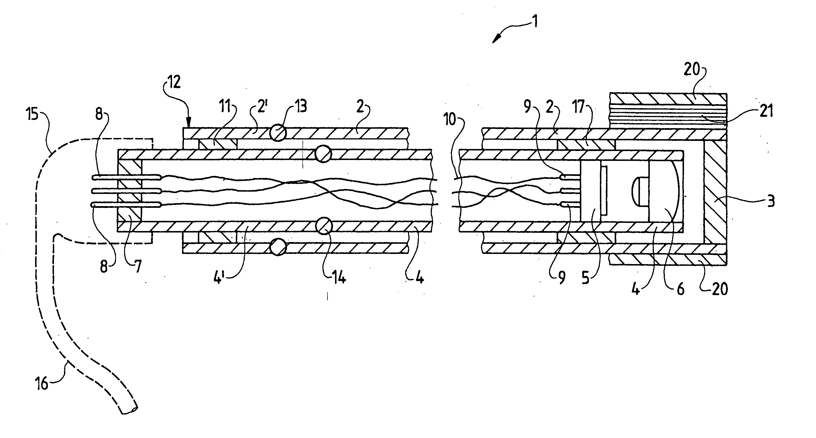
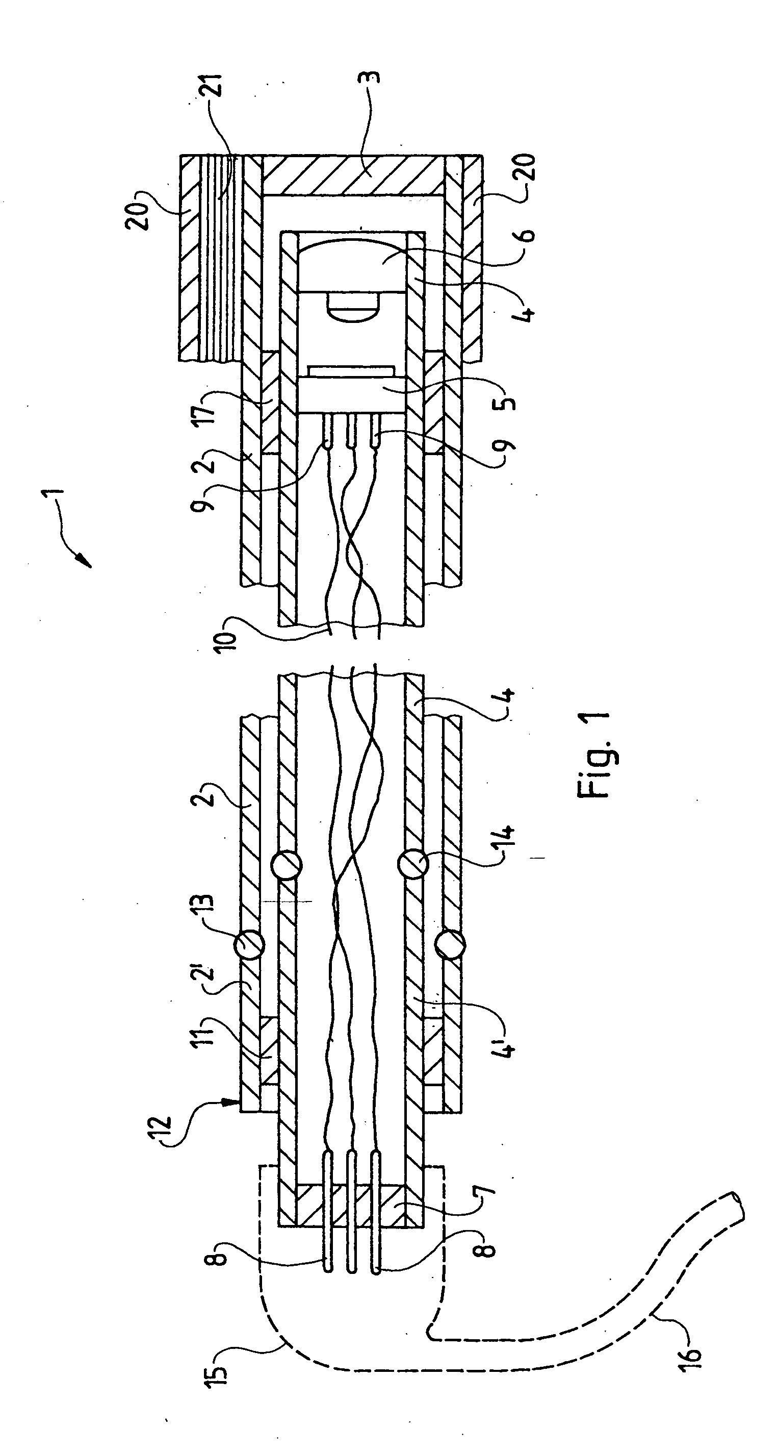
[0011]FIG. 1 is an axial section of a rigid video endoscope of the invention comprising a tube unit 1. Said unit 1 in turn comprises a metallic outer tube 2 fitted with a proximal end segment 2′ and a distal end segment 2 sealed off by a window 3, illustratively hermetically by a rim solder seal. An inner tube 4, 4′ is configured within the outer tube 2, 2′ and also is made of a suitable metal, a video camera 5 of appropriate design fitted with an associated objective 6 being configured in the distal end segment 4 of said inner tube.

[0012] The inner tube is sealed off at its proximal end segment 4′ by a glass fusion element 7 which is traversed by fusion-imbedded contact pins 8. The video camera 5 is fitted with contact pins 9. Electric hookup conductors 10 making contact at both ends run between the contact pins 8 and 9.

[0013] The proximal end segments 4′, 2′ of the two tubes are rigidly joined by glass fusion ring 11 and are sealed off relative to each other. Accordingly the inn...


PUM


Abstract

A rigid video endoscope, fitted with a tube unit (1) comprising a metallic outer tube (2, 2′) sealed off distally by a window (3) and a metallic inner tube (4, 4′) which supports a video camera (5) and an objective (6) in its distal end segment (4), said tube unit being fitted with a proximal terminal part (12) wherein the proximal end segment (4′) of the inner tube (4, 4′) is sealed off by a glass fusion element (7) that is traversed by fusion-imbedded metal contact pins (8) of which the inward ends are connected by conductors (10) to contact pins (9) of the video camera (5) and wherein the proximal end segment (2′) of the outer tube (2, 2′) is hermetically connected to the proximal end segment (4′) of the inner tube (4, 4′), the outer tube (2, 2′) being electrically insulated at least at its distal end segment (2) from the inner tube (2, 2′), is characterized in that the proximal end segments (2′, 4′) of the two tubes (2, 2′; 4, 4′) are connected in the terminal part (12) by means of an annular glass fusion element (11),

Description

BACKGROUND OF THE INVENTION [0001] 1. Field of the Invention [0002] The present invention relates to a video endoscope and moreover to a terminal part for the video endoscope. [0003] 2. Description of Related Art [0004] Video endoscopes of this kind comprise a tube unit including an outer tube fitted with a distal window and hermetically sealed relative to the ambient for the purpose to prevent liquid and vapor from entering the inner space for instance when autoclaving. An inner tube is configured within the outer tube and supports an objective-fitted camera situated in front of the window. The proximal inner tube end is hermetically sealed by a glass fusion element crossed by contact pins serving as electrical terminals to the camera in the inner tube and acting as plug-in connectors on the outside. [0005] For electrical safety, the metallic outer tube must be electrically insulated relative to the inner tube in order to prevent it from making external electrical contact with the ...

Claims


Application Information

Patent Timeline
IPC IPC(8): A61B1/00A61B1/04A61B1/05G02B23/24G02B23/26
CPCA61B1/05A61B1/0008
Inventor MUCKNER, ANDREAS
Owner OLYMPUS WINTER & IBE
Why Eureka
Try Eureka