
Multi-band antenna system

a multi-band antenna and antenna technology, applied in antennas, antenna details, electrical equipment, etc., can solve the problems of increasing production costs and other problems, and achieve the effect of optimizing each service coverage, increasing verticality, and reducing the number of antenna installations

Inactive Publication Date: 2016-04-21
GOODTELL
View PDF3 Cites 7 Cited by
  • Summary
  • Abstract
  • Description
  • Claims
  • Application Information

AI Technical Summary

Benefits of technology

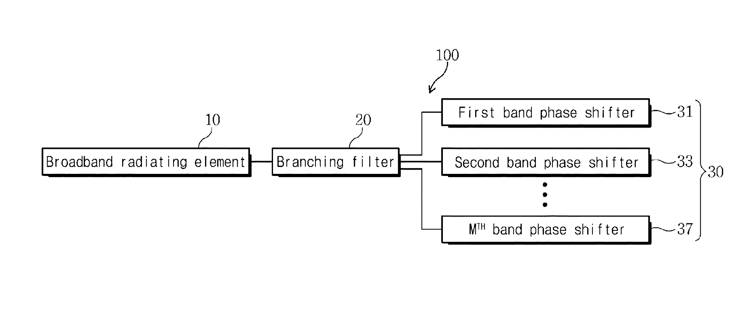
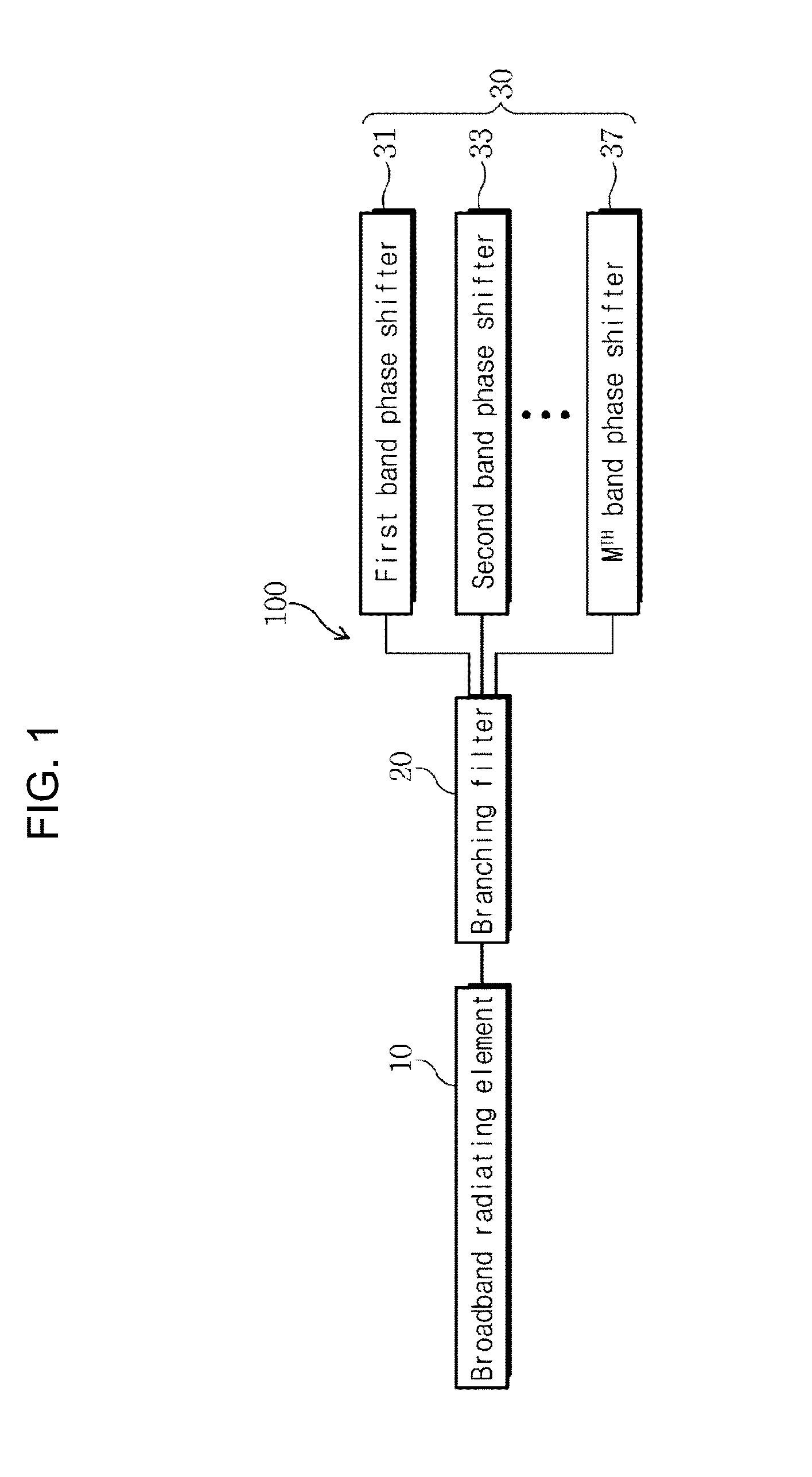
The present invention is a multiband antenna system that branches band-specific signals through a branching filter and performs beam tilting for the branched signals using phase shifters. This optimizes each service coverage. The invention reduces the number of antennas needed, minimizes the increase in size of the antenna system, and ensures isolation between output ports. The phase shifter uses a Wilkinson divider to connect input and output ports, providing isolation between them. The invention also prevents distortion of component or phase signal characteristics.

Problems solved by technology

This causes phase shifters used in the same frequency band to have different sizes, and an increase in production costs.

Method used


Image

  • Multi-band antenna system
  • Multi-band antenna system
  • Multi-band antenna system

Examples


first exemplary embodiment

[0099]In this way, the multiband antenna system 100 branches band-specific signals transmitted and received by the broadband radiating element 10 supporting multiple bands through the branching filter 20, and performs beam tilting for the branched band-specific signals according to the respective bands through the phase shifters 30, thereby optimizing each service coverage.

[0100]Also, the multiband antenna system 100 according to the first exemplary embodiment does not require installation of band-specific antennas for a multiband service, thus reducing the number of installation of antennas.

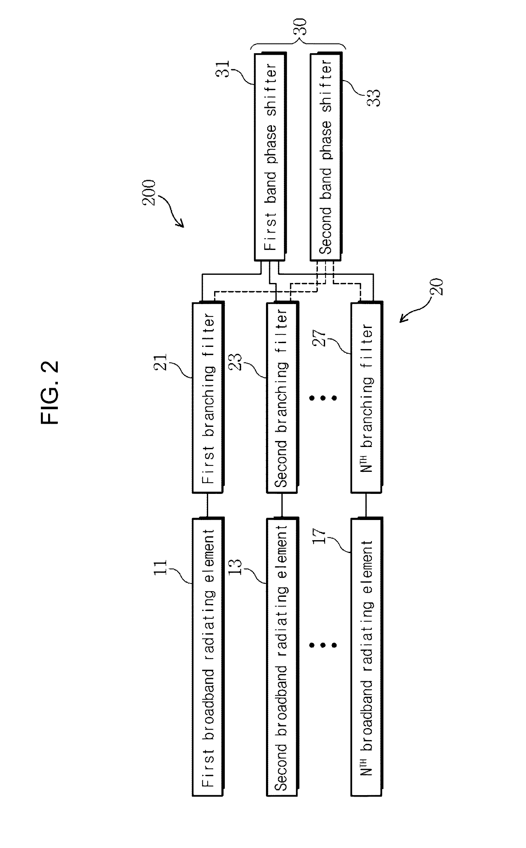
[0101]Meanwhile, the first exemplary embodiment discloses the multiband antenna system 100 including one broadband radiating element 10, but the present invention is not limited thereto. For example, as shown in FIGS. 2 and 3, it is possible to implement multiband antenna systems 200 and 300 including a plurality of broadband radiating elements 10.

[0102]FIG. 2 is a block diagram of the multiban...

second exemplary embodiment

[0104]Here, the branching filters 20 are connected to the plurality of broadband radiating elements 10 to correspond to each other on a one-to-one basis. Therefore, when the number of broadband radiating elements 10 is n (n is a natural number equal to or larger than 2), n branching filters 20 are used. The broadband radiating elements 10 support two bands. For example, the two bands may be a 700 MHz band and a 900 MHz band or a 1.8 GHz band and a 2.1 GHz band. The multiband antenna system 200 according to the second exemplary embodiment includes first, second, . . . , nth broadband radiating elements 11, 13, . . . , and 17.

[0105]As the branching filters 20, diplexers or triplexers can be used. The second exemplary embodiment discloses an example in which diplexers capable of separating two bands are used as the branching filters 20. For example, the multiband antenna system 200 according to the second exemplary embodiment includes first, second, . . . , nth branching filters 21, 2...


PUM


Abstract

The present invention relates to a multiband antenna system and, more particularly, to a multiband antenna system which performs beam tilt while servicing a multiband with a broadband radiating element supporting a multiband. The multiband antenna system according to the present invention comprises: at least one broadband radiating element; a branching filter; and a plurality of phase shifters. The at least one broadband radiating element supports a multiband. The branching filter is connected to each of the at least one broadband radiating element and branches signals per band included in the multiband. The plurality of phase shifters are provided to correspond to the number of the multibands and perform beam tilt for the signals branched per band in accordance with each band. Here, the band means not a band for dividing receipt and transmission in a particular band, but a service band per service provider.

Description

CROSS REFERENCE TO RELATED APPLICATIONS[0001]This application claims the priority of Korean Patent Application No. 10-2013-0060755 filed on May 29, 2013 and Korean Patent Application No. 10-2013-0060756 filed on May 29, 2013 in the Korean Patent and Trademark Office. Further, this application is the National Phase Entry of International Application No. PCT / KR2013 / 009552 filed on Oct. 25, 2013, which is incorporated herein by reference in its entirety.TECHNICAL FIELD[0002]The present invention relates to a multiband antenna system, and more particularly, to a multiband antenna system capable of beam tilting while serving multiple bands with a broadband radiating element supporting the multiple bands.BACKGROUND ART[0003]Due to diversification of communication services, one service provider is allocated a plurality of frequency bands and uses the plurality of frequency bands. Therefore, when a base station or a relay station is installed, antennas according to frequency bands of respec...

Claims


Application Information

Patent Timeline
Patent Type & Authority Applications(United States)
IPC IPC(8): H01Q5/50H01Q5/10
CPCH01Q5/50H01Q3/30H01Q5/00
Inventor PARK, JINYOUNG
Owner GOODTELL
Learn More