Method of mapping csi-rs ports to antenna units, base station and user equipment

a channel state information and reference signal technology, applied in the field of mapping csirs (channel state information reference signal) ports to antenna units, can solve the problems of 64 antenna units being allocated to the csirs ports, not serving these users well, etc., and achieves the effect of good channel estimation performan

Active Publication Date: 2016-04-21
SUN PATENT TRUST
View PDF11 Cites 27 Cited by
  • Summary
  • Abstract
  • Description
  • Claims
  • Application Information

AI Technical Summary

Benefits of technology

[0026]The method, base station, and user equipment of the present disclosure could realize advantages that each antenna unit would get a relatively fair opportunity to perform the CSI-RS port transmission, and get a well channel estimation performance.

Problems solved by technology

Using traditional horizontal beamforming technology can not serve these users very well, so the elevation domain and the horizontal domain both need to consider the beamfoming, which is actually the 3D beamforming.
If it is true that 64 CSI-RS ports are needed for the FD-MIMO, the problem is that in current release 11 of the LTE, only 40 REs (resource element) are used as the CSI-RS ports per PRB.
So how to allocate 64 antenna units to the CSI-RS ports is a problem.

Method used


Image

  • Method of mapping csi-rs ports to antenna units, base station and user equipment
  • Method of mapping csi-rs ports to antenna units, base station and user equipment
  • Method of mapping csi-rs ports to antenna units, base station and user equipment

Examples


first embodiment

1. The First Embodiment

[0052]The first embodiment of the present disclosure is a variable mapping of the antenna units and the CSI-RS ports.

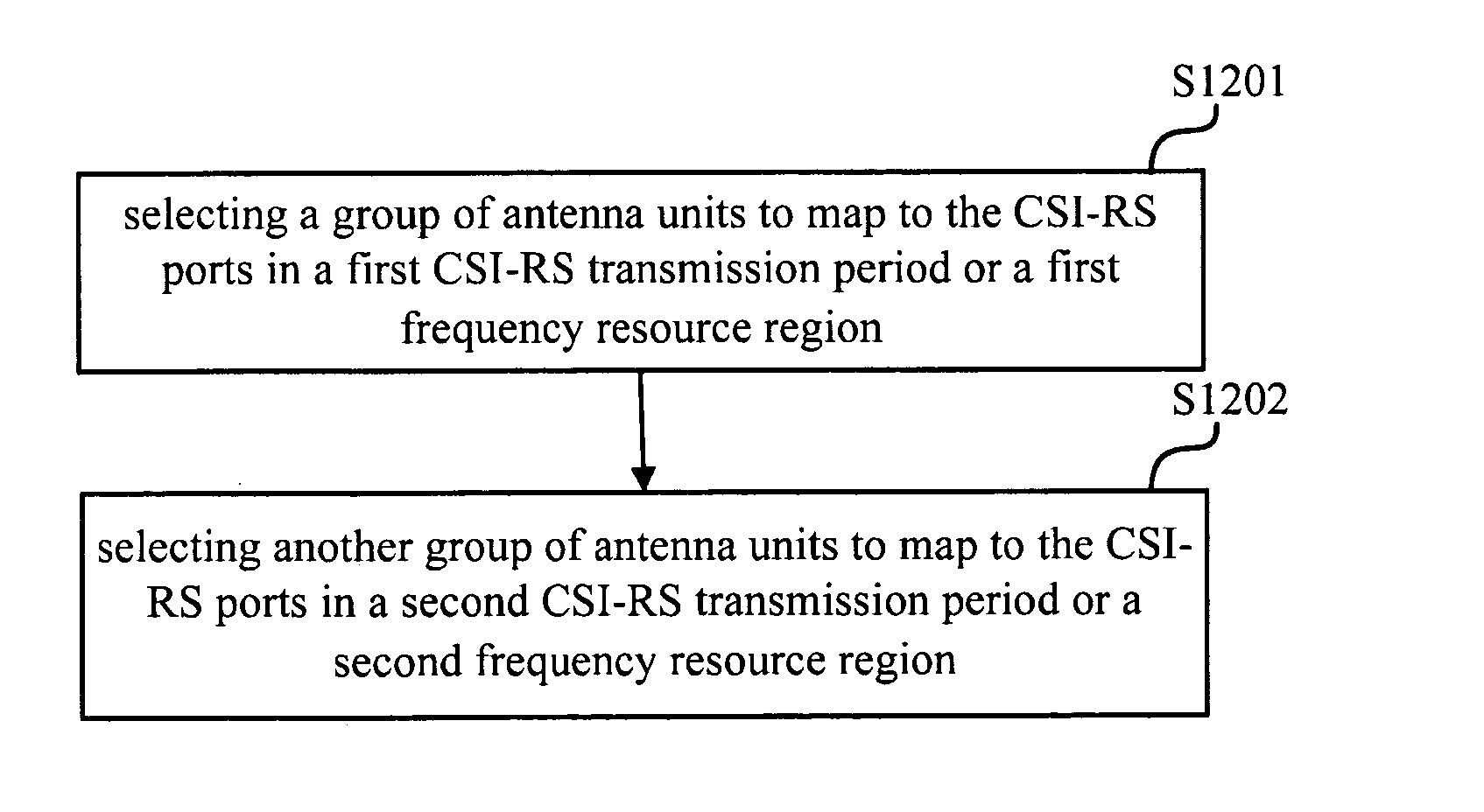
[0053]FIG. 7 is a block diagram schematically showing a base station (eNB) 700 according to an embodiment of the present disclosure. In the present embodiment, the eNB 700 has a function of mapping the CSI-RS ports to the antenna units arranged in an antenna array system. The eNB 700 comprises a mapping unit 701 which is configured to select a group of antenna units to map to the CSI-RS ports in a first CSI-RS transmission period or a first frequency resource region, and select another group of antenna units to map to the CSI-RS ports in a second CSI-RS transmission period or a second frequency resource region.

[0054]FIG. 8A and FIG. 8B show variable antenna unit-CSI-RS port mapping according to the first embodiment of the present disclosure. Specifically, FIG. 8A shows antenna unit-CSI-RS port mapping variable in time domain according to the fir...

second embodiment

2. The Second Embodiment

[0069]The second embodiment is that the applied CSI-RS port-antenna unit mapping pattern could be more distributed instead of one column and one row always.

[0070]FIG. 9 shows a variable antenna unit-CSI-RS port mapping according to the second embodiment of the present disclosure.

[0071]According to the second embodiment of the present disclosure, the mapping unit 701 (as shown in FIG. 7) may select a group of antenna units to map to the CSI-RS ports in a first CSI-RS transmission period or a first frequency resource region, and select another group of antenna units to map to the CSI-RS ports in a second CSI-RS transmission period or a second frequency resource region, in which the antenna units in each group may be more separately distributed in frequency domain or time domain.

[0072]Specifically, in the second embodiment of the present disclosure, a part of CSI-RS ports mapping the antenna units may reflect a first channel vector, and another part of CSI-RS po...

third embodiment

3. The Third Embodiment

[0077]The third embodiment of the present disclosure is that differentiated allocation patterns for two orthogonal CSI-RS resources are used.

[0078]FIG. 10 shows different allocation patterns for the CSI-RS resources reflecting different orthogonal channel vectors according to the third embodiment of the present disclosure.

[0079]In FIG. 10, there are shown a plurality of physical resource blocks (PRB) arranged in the frequency domain, and two orthogonal CSI-RS resources reflecting horizontal channel vectors and vertical channel vectors are also shown. As shown in the FIG. 10(a), a group of CSI-RS resources 1-7 reflecting the horizontal channel vectors indicated by slash line “I” and another group of CSI-RS resources 1-7 reflecting the vertical channel vectors indicated by slash line “\” are evenly used.

[0080]However, in some scenarios, the vertical domain channel may be more flat than the horizontal domain channel. In this connection, according to the third emb...


PUM


Abstract

The present disclosure provides a communication method of mapping CSI-RS ports to antenna units arranged in an antenna array system, a base station, and a user equipment, the communication method comprises steps of: selecting a group of antenna units to map to the CSI-RS ports in a first CSI-RS transmission period or a first frequency resource region; and selecting another group of antenna units to map to the CSI-RS ports in a second CSI-RS transmission period or a second frequency resource region. By the method, base station, and user equipment according to the present disclosure, each antenna unit would get a relatively fair opportunity for transmitting the CSI-RS signals or get a fairly good channel estimation performance in UE side.

Description

TECHNICAL FIELD[0001]The present disclosure relates to a method of mapping CSI-RS (channel state information-reference signal) ports to antenna units in FD-MIMO (full dimension multiple-input multiple-output) communication system in LTE (Long Term Evolution).BACKGROUND ART[0002]Beamforming which is a kind of multiple antenna technology has been already adopted in early Long Term Evolution (LTE) standard release to enhance the coverage throughput. With respect to this technology, people were mainly focusing on azimuth domain so far. For example, how to form a horizontal beam using a certain weighting vector has been studied. In elevation domain, a fixed downtilt instead of a certain dynamic beam is supported in current LTE system.[0003]With the increase of requirement on the elevation domain beamforming, 3D beamforming seems more and more important especially in urban area, in which users locate on different floors of the building. Using traditional horizontal beamforming technology ...

Claims


Application Information

Patent Timeline
Patent Type & Authority Applications(United States)
IPC IPC(8): H04L5/00H04W72/04H04B7/04H04L1/00H04W16/28
CPCH04L5/0048H04L1/0026H04W72/042H04B7/0456H04W16/28H04L5/0023H04L5/005H04L5/006H04L5/0094H04L25/0224H04W72/23
Inventor XU, MINGHOSHINO, MASAYUKINISHIO, AKIHIKOTAKEDA, KAZUKIWANG, LILEI
Owner SUN PATENT TRUST
Why Eureka
Try Eureka