Iterative estimator and method of channel and noise variance for multiple input multiple output orthogonal frequency division multiplexing system

a multiplexing system and orthogonal frequency division technology, applied in the field of iterative transmission/reception, can solve the problems of difficult to embody the joint channel estimation scheme, high complexity of the system, and significant deterioration of the performance, and achieve the effect of low complexity

Inactive Publication Date: 2011-06-30
ELECTRONICS & TELECOMM RES INST
View PDF4 Cites 15 Cited by
  • Summary
  • Abstract
  • Description
  • Claims
  • Application Information

AI Technical Summary

Benefits of technology

[0010]An aspect of the present invention provides a transmission / reception apparatus and method that can adopt a channel estimation scheme with similar performance to a joint channel estimation scheme and with lower complexity due to not requiring a matrix inversion, in a Multiple-Input Multiple-Output (MIMO) orthogonal frequency division multiplexing (OFDM) system.

Problems solved by technology

Generally, since P>50, it is very difficult to embody the joint channel estimation scheme.
However, since the conventional scheme does not adopt a time domain channel estimation process, the performance may be significantly deteriorated when frequency selectivity or time selectivity is large.
However, since the mixed scheme also requires P×P matrix inversion for each OFDM symbol, there still remains a problem that the complexity thereof is very high.
In the case of an initial channel estimation scheme of estimating a channel using a pilot symbol, a channel estimation value in a previous iteration for interference cancellation does not exist and thus the interference cancellation becomes impossible.
In the case of a conventional noise variance estimation scheme, when per-subcarrier estimation is performed, the performance can be deteriorated due to a noise component.

Method used


Image

  • Iterative estimator and method of channel and noise variance for multiple input multiple output orthogonal frequency division multiplexing system
  • Iterative estimator and method of channel and noise variance for multiple input multiple output orthogonal frequency division multiplexing system
  • Iterative estimator and method of channel and noise variance for multiple input multiple output orthogonal frequency division multiplexing system

Examples


Embodiment Construction

[0025]Reference will now be made in detail to embodiments of the present invention, examples of which are illustrated in the accompanying drawings, wherein like reference numerals refer to the like elements throughout. The embodiments are described below in order to explain the present invention by referring to the figures.

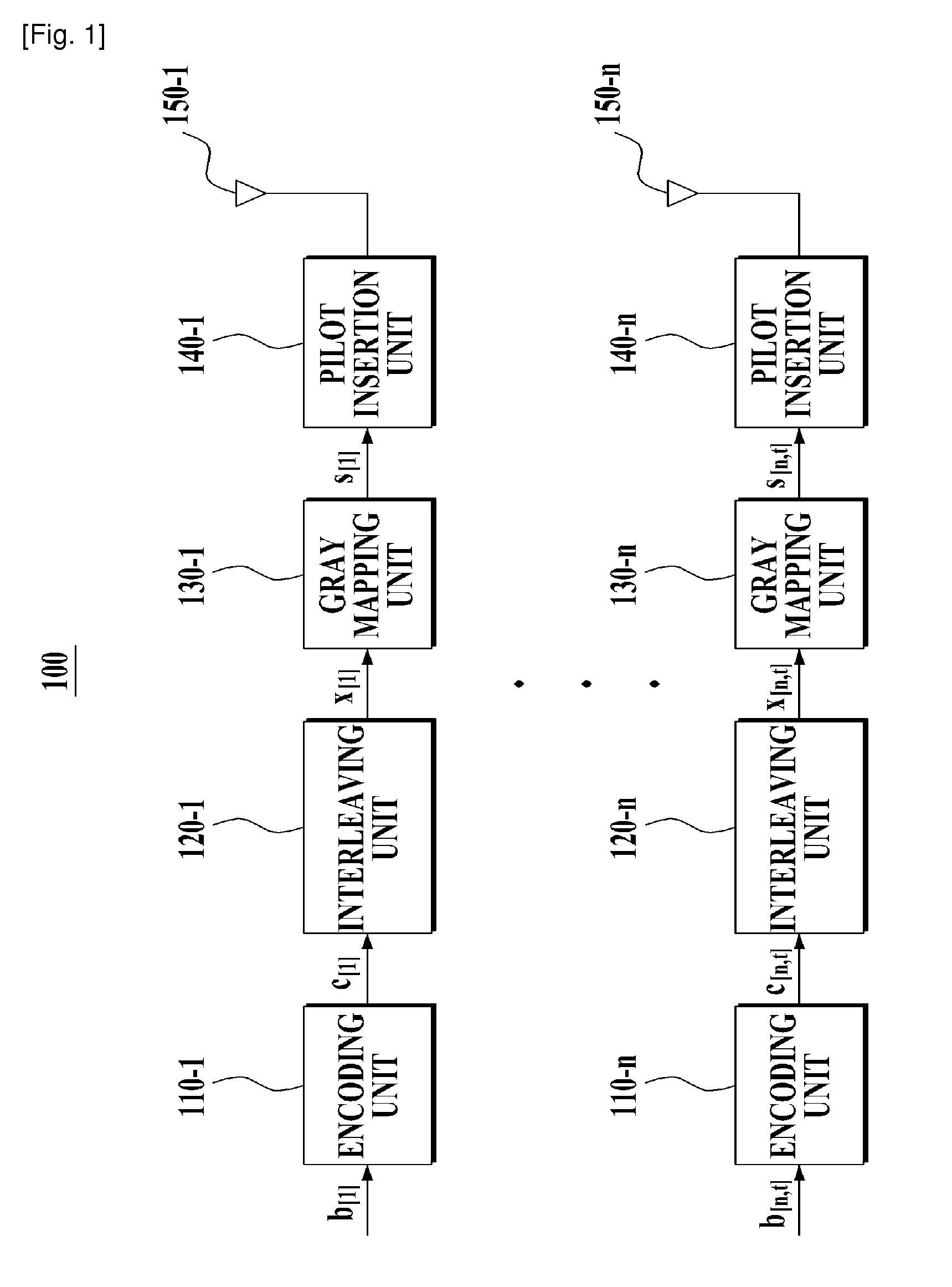
[0026]Hereinafter, an iterative transmission / reception apparatus and method for a Multiple-Input Multiple-Output (MIMO) orthogonal frequency division multiplexing (OFDM) system will be described in detail with reference to the accompanying drawings. For example, the present invention will be described based on the MIMO OFDM system with Nt transmit antennas and Nr receive antennas. Here, a total number of subcarriers is N in which Nc subcarriers are used to substantially transmit data and N-Nc subcarriers are not used. Among the Nc effective subcarriers, Np subcarriers are allocated to a pilot symbol and remaining subcarriers are allocated to an information symbol....


PUM


Abstract

A reception apparatus including: a detection unit detecting extrinsic information based on an output of a tentative symbol decision unit, an output of a channel estimation unit, and an output of a noise variance estimation unit that are obtained from a previous iteration process; a Cyclic Redundancy Check (CRC) aided channel decoding unit outputting an encoded and interleaved bit, or a posteriori information thereof based on the extrinsic information; the tentative symbol decision unit determining a tentative transmission symbol based on an output of the CRC aided channel decoding unit; the channel estimation unit estimating a channel based on an output of the tentative symbol decision unit or a pilot symbol; and the noise variance estimation unit estimating a noise variance or an initial noise variance based on the output of the tentative symbol decision unit and the output of the channel estimation unit is provided.

Description

TECHNICAL FIELD[0001]The present invention relates to an iterative transmission / reception apparatus and method for improving the performance associated with channel estimation and noise variance estimation and reducing the complexity in a Multiple-Input Multiple-Output (MIMO) orthogonal frequency division multiplexing (OFDM) system.[0002]This work was supported by the IT R&D program of MIC / IITA. [2006-S-001-02, Development of Adaptive Radio Access and Transmission Technologies for 4th Generation Mobile Communications]BACKGROUND ART[0003]Generally, compared to a scheme of directly estimating a frequency domain channel in a received signal, a Multiple-Input Multiple-Output (MIMO) orthogonal frequency division multiplexing (OFDM) system initially estimates a time domain channel and then finally estimates a frequency domain channel using the estimated time domain channel. The MIMO OFDM system can reduce the noise affect and also can effectively perform interpolation between pilot subcar...

Claims


Application Information

Patent Timeline
Patent Type & Authority Applications(United States)
IPC IPC(8): H04B17/00
CPCH04B7/0413H04L1/0048H04L1/005H04L1/0061H04L25/03324H04L25/0228H04L25/0236H04L25/0242H04L25/0204H04L5/0007
Inventor KIM, SEONG RAGNAM, JUNYOUNGCHUNG, HYUN KYU
Owner ELECTRONICS & TELECOMM RES INST
Why Eureka
Try Eureka