Electronic atomization device

a technology of atomization device and atomizer, which is applied in the direction of ohmic-resistance electrodes, ohmic-resistance heating details, tobacco, etc., can solve the problems of user's hands dirty with tobacco tar and inconvenient disassembly, and achieves convenient change and good safety and health performan

Inactive Publication Date: 2016-04-28
SHENZHEN JIESHIBO TECH
View PDF0 Cites 107 Cited by
  • Summary
  • Abstract
  • Description
  • Claims
  • Application Information

AI Technical Summary

Benefits of technology

[0005]An object of the present invention is to provide an electronic atomization device provided with an atomization core easy to be changed so as to overcome the defects

Problems solved by technology

However, for the existing atomization device, its atomization core and its airway tube are generally assembled together by threaded connection or

Method used


Image

  • Electronic atomization device
  • Electronic atomization device
  • Electronic atomization device

Examples


first embodiment

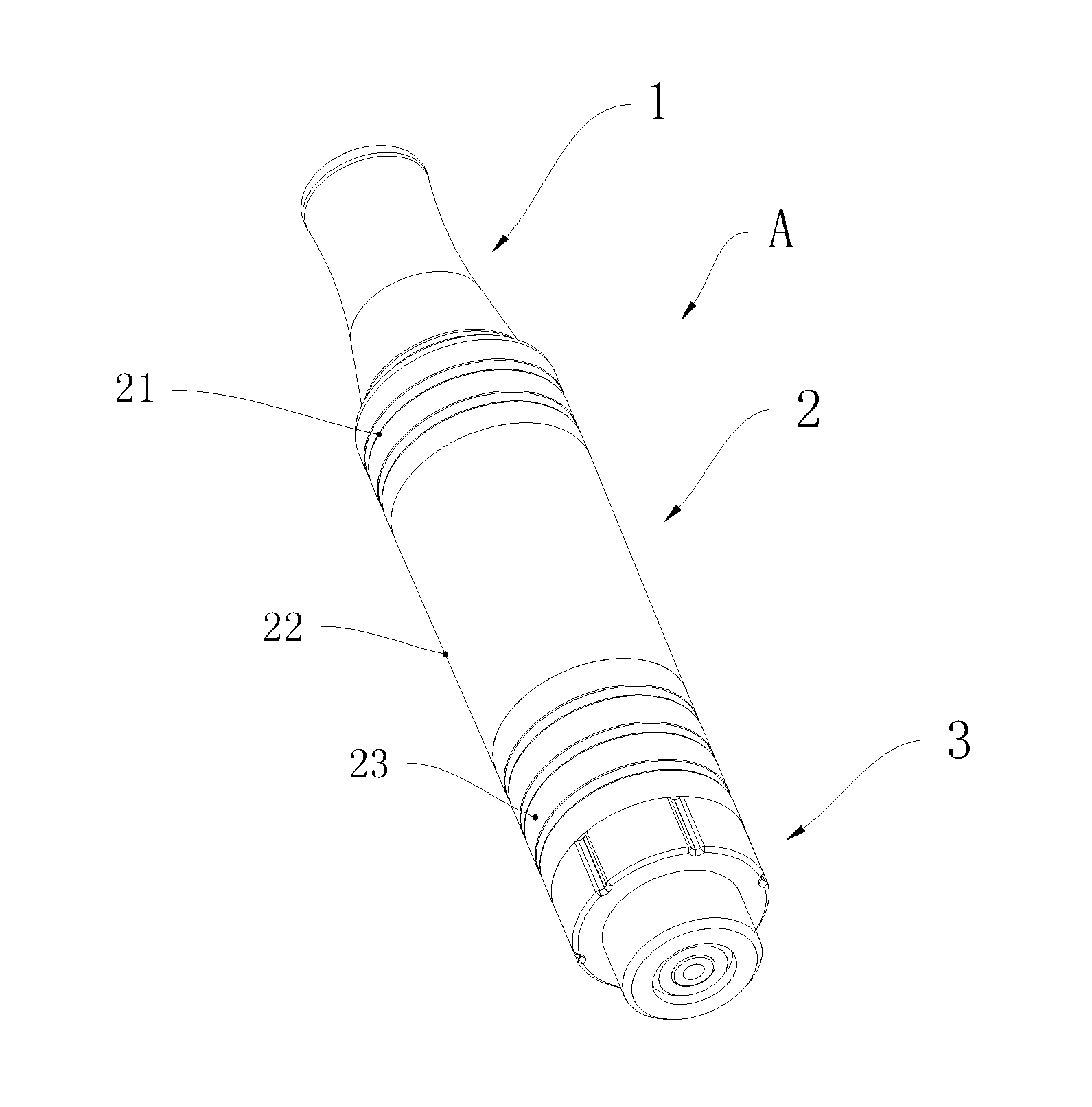
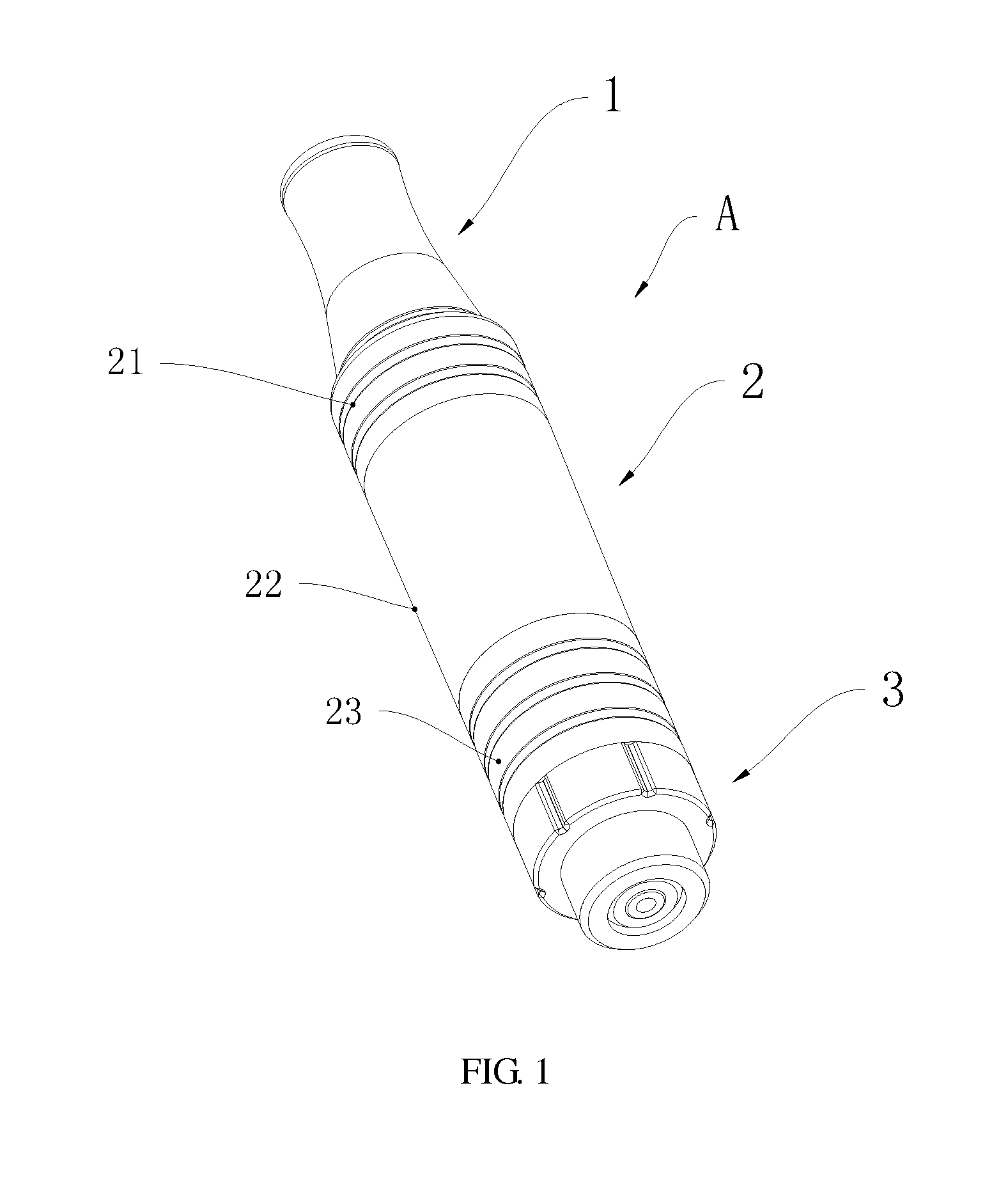
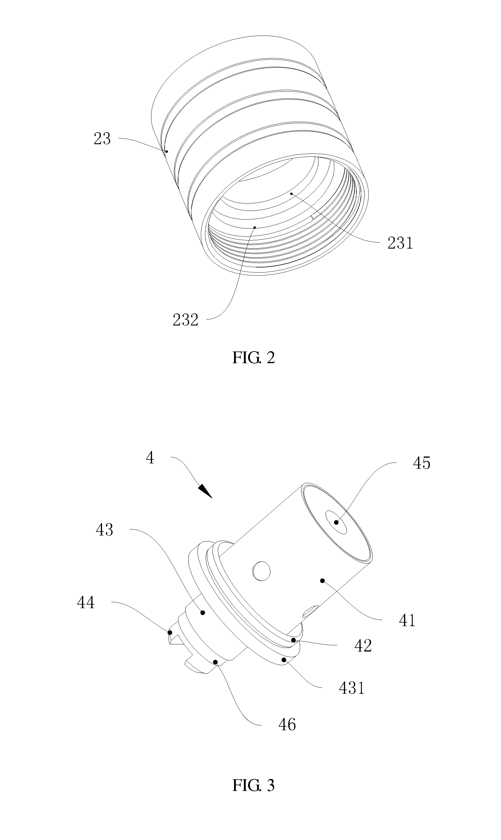
[0022]FIG. 1 to FIG. 4 shows the present invention. As shown from FIG. 1 to FIG. 4, the electronic atomization device includes a suction nozzle 1, an oil cup assembly 2, an atomization core assembly 4 disposed in the oil cup assembly 2 and an electrode assembly 3 electrically connected with the atomization core assembly 4. The atomization core assembly 4 includes a heater support 43 provided with a first stepped structure 431, an atomization core body 41 supported by the heater support 43, a sealing washer 42 sleeved on the atomization core body 41 and closely contacting with the first stepped structure 431 for avoiding oil leakage, an electrode connecting part 44 connected with an end of the heater support 43 via an insulating ring 46, and an air hole connecting part 45 disposed in the atomization core body 41. The oil cup assembly 2 includes an oil cup body 22, a first connecting element 21 removably connected with the suction nozzle 1 and a second connecting element 23 removably ...

second embodiment

[0026]FIG. 5 to FIG. 6 shows the present invention. In this embodiment, there is at least one protrusion 211 made of elastic material provided on an outside surface of the first connecting element 21 so as to improving hand feeling. In this preferred embodiment, the protrusion 211 includes a long strip body 211a and a plurality of convex bumps 211b formed on a surface of the long strip body 211a. The protrusion 211 could be made of rubber or silicon.

[0027]Now the assembling process of the electronic atomization device of the present invention will be described as follows:

[0028]Firstly, insert the atomization core assembly 4 into the second connecting element 23; screw the electrode assembly 3 onto the second connecting element 23 tightly, during screwing, the sealing washer 42 being pressed onto the second stepped structure 231 tightly so that the air hole connecting part 45 is hermetically connected with the airway tube disposed in the oil cup body 22; continue to screw the electro...


PUM


Abstract

Disclosed is an electronic atomization device, which includes a suction nozzle, an oil cup assembly, an atomization core assembly and an electrode assembly. The atomization core assembly includes a heater support with a first stepped structure, an atomization core body supported by the heater support, a sealing washer sleeved on the atomization core body and closely contacting with the first stepped structure, an electrode connecting part connected with an end of the heater support via an insulating ring and an air hole connecting part disposed in the atomization core body. The oil cup assembly includes an oil cup body having an airway tube for connecting with the air hole connecting part, a first connecting element removably connected with the suction nozzle and a second connecting element having a second stepped structure formed therein for fitting the sealing washer. According to the present invention, its atomization core is easy to be changed.

Description

CROSS-REFERENCE TO RELATED APPLICATIONS[0001]This present invention claims the benefit of Chinese Patent Application No. CN201420624028.8, filed on Oct. 24, 2014; the contents of which are hereby incorporated by reference.FIELD OF THE INVENTION[0002]The present invention relates to electronic atomization device, in particular, it concerns an electronic atomization device which has an atomization core easy to be changed.BACKGROUND OF THE INVENTION[0003]Electronic atomization device, also called electronic cigarette or atomization tobacco with low temperature, is mainly used for reducing harm brought by smoking traditional cigarette. Its appearance and taste are similar to cigarette and it has more flavors than even normal cigarette does. It can also create a cloud, a taste and a feel that resemble cigarette. The electronic atomization device, which is composed of battery assembly and atomizer, is an imitative cigarette, and flavor components therein can be atomized into gas by atomiz...

Claims


Application Information

Patent Timeline
IPC IPC(8): A24F47/00H05B3/03A24F40/10A24F40/40
CPCH05B3/03A24F47/008H05B3/06A24F40/10A24F40/40
Inventor WU, JIANYONG
Owner SHENZHEN JIESHIBO TECH
Why Eureka
Try Eureka