Hydrostatic pressure guide mechanism and machine tool

Active Publication Date: 2016-04-28
TOSHIBA MASCH CO LTD +1
View PDF0 Cites 7 Cited by
  • Summary
  • Abstract
  • Description
  • Claims
  • Application Information

AI Technical Summary

Benefits of technology

[0045]With this arrangement, while the equipment can be simplified by the common use of the oil supply structure and the oil recovery structure, a hydraulic pressure of each system of the hydrostatic pressure guide mechanisms can be minutely adjusted by independent hydraulic control valves in the each system. Such an adjustment of the each system cannot be conducted so minutely as an adjustment of each of the hydrostatic pressure guide mechanisms, however, the number of the

Problems solved by technology

Specifically, the guiding accuracy of the guide mechanism affects a positioning accuracy of the two relatively movable members, thereby affecting a profile accuracy of a workpiece to be machined.
The low friction of the guide mechanism affects the positioning accuracy along a movement axis, thereby affecting the profile accuracy of the workpiece to be machined.
Moreover, vibration resistance affects damping of vibration between the two relatively movable members.
Specifically, damping level of

Method used


Image

  • Hydrostatic pressure guide mechanism and machine tool
  • Hydrostatic pressure guide mechanism and machine tool
  • Hydrostatic pressure guide mechanism and machine tool

Examples


Example

First Exemplary Embodiment

[0080]FIGS. 1 to 8 show the first exemplary embodiment of the invention.

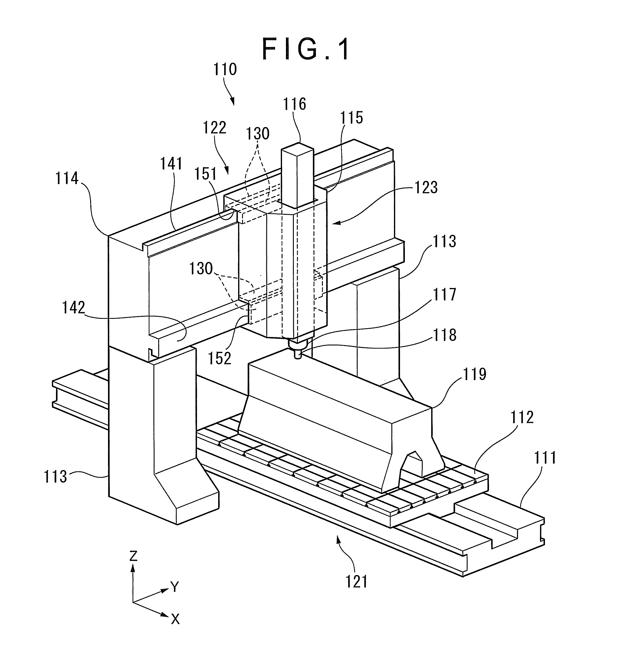
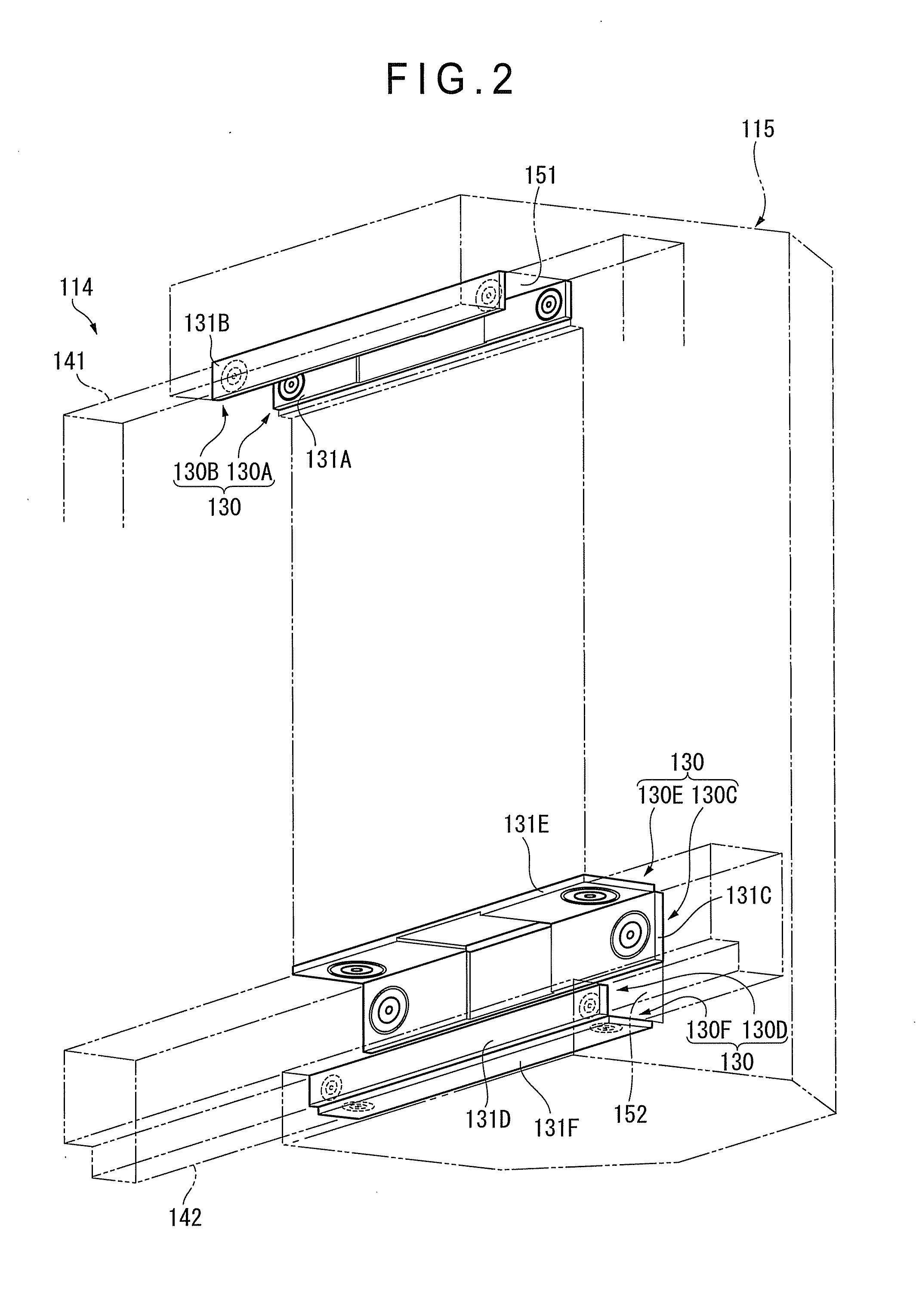
[0081]In the first exemplary embodiment, a hydrostatic pressure guide mechanism is used as a guide mechanism for X-axis movement mechanism, Y-axis movement mechanism and Z-axis movement mechanism in a portal-structured machine tool 110 as shown in FIGS. 1 and 2.

[0082]As shown in FIG. 1, the machine tool 110 includes a platform 111 extending in the X-axis direction and a table 112 supported by the platform 111. A pair of columns 113 are provided on both sides of the platform 111. A cross bar 114 extends in the Y-axis direction between upper ends of the columns 113. A head 115 is supported by the cross bar 114. A ram 116 extending in the Z-axis direction (vertical direction) is attached to the head 115.

[0083]A workpiece 119, which is an object to be machined, is fixed on a top surface of the table 112. A main spindle 117 is exposed from a lower end of the ram 116. A machining tool 118 is ...

Example

Second Exemplary Embodiment

[0127]FIGS. 9 to 13 show a second exemplary embodiment of the invention.

[0128]It should be noted that, in the second exemplary embodiment, a configuration identified with or corresponding to the configuration of the hydrostatic pressure guide mechanism 1 in the first exemplary embodiment will be described with the same reference numerals. Moreover, the description on the configuration in the first exemplary embodiment is occasionally incorporated herein in order to describe the configuration identified with or corresponding to the configuration in the first exemplary embodiment.

[0129]As shown in FIGS. 9 and 12, the hydrostatic pressure guide mechanism 1 in the exemplary embodiment also includes: the guide member 29 having the guide surface 28; and the movement member 2 having the slide surface 20.

[0130]As shown in FIGS. 10 and 11, the movement member 2 includes: the annular placement groove 21 formed on the slide surface 20; the seal member 3 that is an an...

Example

Third Exemplary Embodiment

[0152]FIGS. 14 to 17 show a third exemplary embodiment of the invention.

[0153]It should be noted that, in the third exemplary embodiment, a configuration identified with or corresponding to the configuration of the hydrostatic pressure guide mechanism 1 in the first exemplary embodiment will be described with the same reference numerals. Moreover, the description on the configuration in the first exemplary embodiment is occasionally incorporated herein in order to describe the configuration identified with or corresponding to the configuration in the first exemplary embodiment.

[0154]As shown in FIG. 16, the hydrostatic pressure guide mechanism 1 in the third exemplary embodiment also includes: the guide member 29 having the guide surface 28; and the movement member 2 having the slide surface 20.

[0155]As shown in FIGS. 14 and 15, the movement member 2 includes: the annular placement groove 21 formed on the slide surface 20; the seal member 3 that is an annul...


PUM


Abstract

A hydrostatic pressure guide mechanism includes: a guide member having a smooth guide surface; a movement member having a slide surface facing the guide surface and an annular placement groove formed on the slide surface; an annular seal member (hermetically closing member) that is disposed in the placement groove and capable of hermetically contacting with the guide surface; an oil supply structure configured to supply an oil into a static pressure pocket on the slide surface surrounded by the seal member; and an oil recovery structure configured to recover the oil from the static pressure pocket, in which the oil recovery structure has a recovery hole that is formed in the static pressure pocket and is opened on the slide surface.

Description

[0001]The entire disclosure of Japanese Patent Application No. 2014-219651 filed Oct. 28, 2014 is expressly incorporated by reference herein.TECHNICAL FIELD[0002]The present invention relates to a hydrostatic pressure guide mechanism and a machine tool, more specifically, to a hydrostatic pressure guide mechanism capable of smoothly guiding a guide member and a movement member, which are mutually relatively movable, with a high accuracy while supporting a load using hydrostatic pressure between the guide member and the movement member by supplying oil between the guide member and movement member, and a machine tool provided with the hydrostatic pressure guide mechanism.BACKGROUND[0003]Typically, various movement mechanisms are used in the machine tool in order to move a workpiece (an object to be machined) and a tool for machining the workpiece to any relative positions.[0004]For instance, linear movement mechanisms are provided in respective X axis, Y axis and Z axis to a support s...

Claims


Application Information

Patent Timeline
IPC IPC(8): F16C29/02B23Q1/56B23Q1/38
CPCF16C29/025B23Q1/56B23Q1/38
Inventor TADA, ATSUSHISAGARA, MAKOTOTSUKIJI, TERUAKIARAI, TAKAO
Owner TOSHIBA MASCH CO LTD
Why Eureka
Try Eureka