
Method and system for creating mailpieces from a single continuous web of printed material

Active Publication Date: 2006-08-24
DMT SOLUTIONS GLOBAL CORP
View PDF26 Cites 8 Cited by
  • Summary
  • Abstract
  • Description
  • Claims
  • Application Information

AI Technical Summary

Benefits of technology

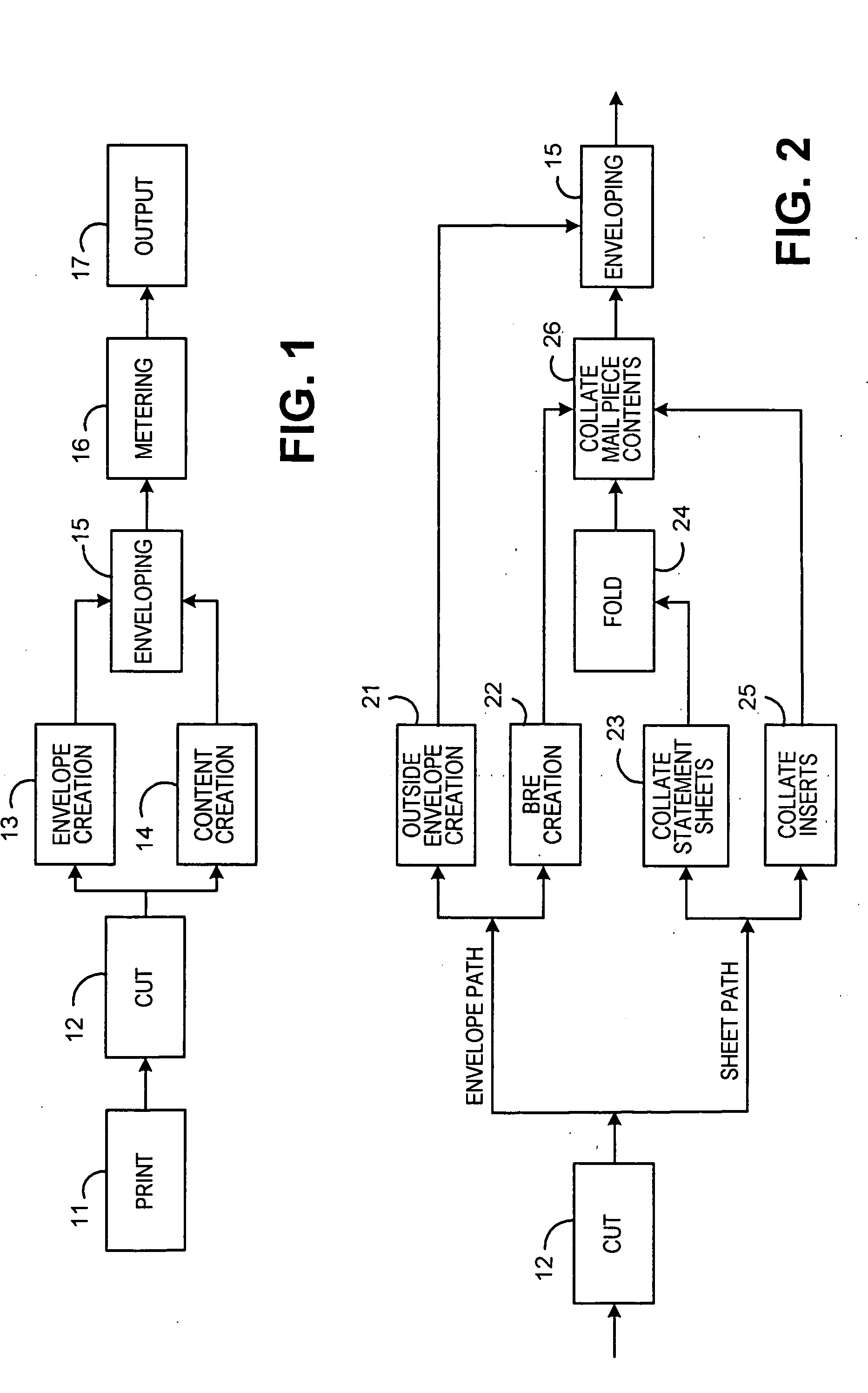
[0013] Fourth, when mail pieces are created from discrete elements, each of these elements must be fed, registered, transported, etc. Each of these steps introduces additional potential for malfunctions. A machine to create mail without at least some of the traditional steps will be more reliable. It would be beneficial if more elements of the mail piece could be cut from a continuous web, for example a roll, of paper in order to eliminate the unreliability of feeding and registering these components.
[0015] This proposed method and system addresses these limitations of the current mail creation equipment. It simplifies the equipment by eliminating a number of sub-systems required in the current equipment such as dedicated feeders for each of the mail piece elements, it improves reliability by eliminating some of the more trouble prone steps such as feeding and inserting. It saves “back office” costs associated with separately ordering, shipping, warehousing, and handling multiple elements typically included in the mail pieces. (Only a single continuous web of printed material must be ordered prior to the job; and in some implementations, the web could be ordered blank and printed using a printer that is on-line to the mail creation process.) The proposed method and system generally simplifies the entire mail creation process. And it enables automatic creation of multiple types of mail pieces in the same job and eliminates the steps of handling different types of mail pieces in separate processes.
[0016] With regard to simplification of the equipment, an example of a subsystem that can be eliminated by the present invention is the addressing subsystem. In a conventional system, addresses are typically printed on the envelopes by a separate imaging system, such as a high speed ink jet printer. As described below, the present invention enables addressing by the same imaging system that prints the mailpiece contents. Thus the present invention allows simplification by eliminating a subsystem, and saves the associated costs of labor and supplies.
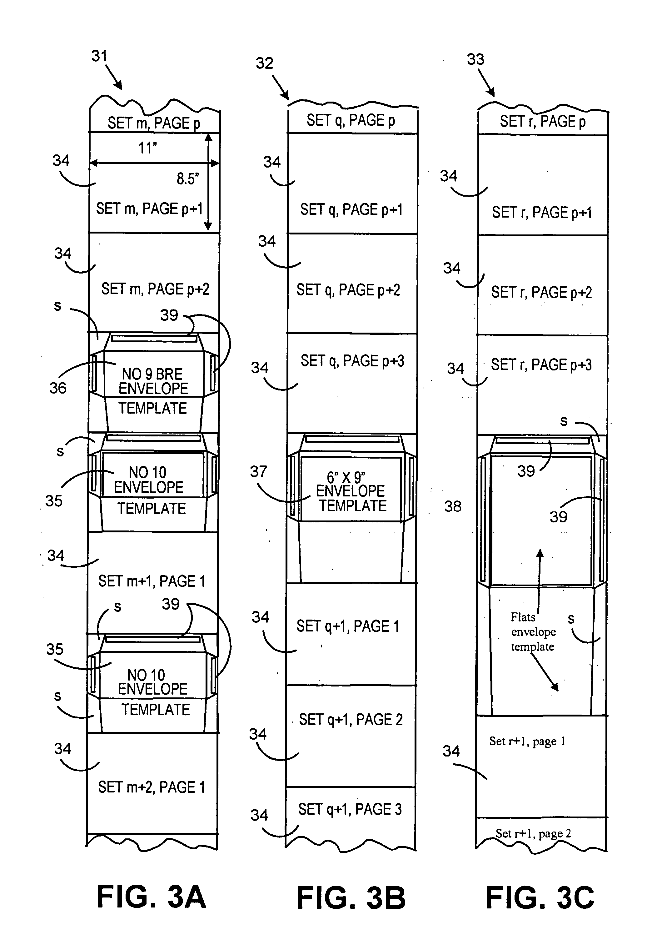
[0023] In another preferred embodiment, the step of cutting variable sized and shaped sheets includes using a laser cutter to cut the variable sized and shaped sheets. The step of using a laser cutter for variable size and shape cutting may also include continuously moving the web of printed material without stopping while cuts are being made. Laser cutting also allows for cutting of mailpiece specific features into the sheets.

Problems solved by technology

The current generation of high speed mail creation equipment has a number of limitations.
First, the current generation of high speed mail creation equipment is quite expensive and complicated.
The dedicated processing for each of the elements of the mail pieces is one of the reasons why the mail creation equipment is so expensive and complicated.
Secondly, it is known that the step of inserting the contents of the mail piece into the envelope is a trouble prone step in the mail creation process.
Thirdly, in the current equipment, each of the mail piece components must be sourced or created separately, and brought to the mail creation equipment for loading just prior to running the job.
Each of these steps involves labor and expenses that are properly part of the cost of creating the mail pieces.
Each of these steps introduces additional potential for malfunctions.

Method used


Image

  • Method and system for creating mailpieces from a single continuous web of printed material
  • Method and system for creating mailpieces from a single continuous web of printed material
  • Method and system for creating mailpieces from a single continuous web of printed material

Examples


Embodiment Construction

[0035] The in-line envelope solution in accordance with the present invention is a method or system that creates a complete mailpiece from one continuous paper stream. For a given mailpiece, the paper stream contains variable numbers of pages, variable size documents (including inserts), an optional BRE, and the envelope. The machine cuts and folds the documents and envelopes, creates the envelope and BREs, and assembles the mailpiece in one self-contained system.

[0036] The present invention may be used advantageously with improved color Variable Data Printing (VDP), allowing graphical, color content to be printed in-line with text. With increased use of color VDP technology, sophisticated mail communications can be printed in a single step onto a continuous web of material. The present invention provides a method for handling that continuous web to more efficiently produce finished mailpieces.

[0037] Adopting color VDP printing techniques with the present invention will allow effi...


PUM

PropertyMeasurementUnit
Timeaaaaaaaaaa
Dimensionaaaaaaaaaa
Contentaaaaaaaaaa

Abstract

A method for creating mailpieces from a single web of printed material. The web of printed material includes printed matter to be used on envelopes, and other printed matter to be used on mail content to be included in the envelopes. The content pages are rectangular in shape and may be oriented relative to the envelope sheets in a number of different configurations. In some configurations, two sets of content pages and / or envelope sheets can be printed across the width of the web. The method starts with cutting consecutive sections of the web into separated sheets. Some of the separated sheets are envelope sheets including envelope printed matter, and some of the sheets are mail content sheets including mail content printed matter. The method includes cutting variable sized sheets depending on whether a sheet is a mail content sheet, or an envelope sheet. The method further includes cutting variable sized envelope sheets depending on the size of the mailpieces. In a preferred embodiment, the web includes business return envelopes (BREs). The BRE sheets are transported to an envelope creation path and in the envelope creation path where the sheets are formed into envelopes. The envelope creation path is then merged back with a content processing path whereby finished BRE's are stacked with their respective accumulations of folded content sheets to form a complete content stack. BRE's are then enclosed with the content sheets by the enclosing envelope sheets.

Description

FIELD OF THE INVENTION [0001] The present invention relates generally to a mail creation system that uses an input of a single web of paper to create content and envelopes for creation and mass-production of a finished mailpieces. BACKGROUND OF THE INVENTION [0002] Inserter systems are typically used by organizations such as banks, insurance companies and utility companies for producing a large volume of specific mailings where the contents of each mail item are individualized to a particular addressee. Also, other organizations, such as direct mailers, use inserters for producing a large volume of generic mailings where the contents of each mail item are substantially identical for each addressee. Examples of such inserter systems are the 8 series, 9 series, and APS™ inserter systems available from Pitney Bowes Inc. of Stamford, Conn. [0003] In many respects, the typical inserter system resembles a manufacturing assembly line. Sheets and other raw materials (other sheets, enclosure...

Claims


Application Information

Patent Timeline
IPC IPC(8): B65B63/04B65B11/48B31B50/16
CPCB31B19/26B31B21/00B31B2219/2672B31B2221/05B31B2221/10B65B11/00B43M5/04B42C3/00B42D5/025B42D15/08B31B70/261B31B2150/00B31B2160/10B31B2170/20
Inventor WOODMAN, CLARE E.STEMMLE, DENIS J.SUSSMEIER, JOHN W.BELEC, ERIC A.ROZENFELD, BORISSKINGER, GREGORY P.CUMMINGS, MICHAEL J.
Owner DMT SOLUTIONS GLOBAL CORP
Learn More