Ice-shedding spinner for ram air turbine

Active Publication Date: 2016-05-05
HAMILTON SUNDSTRAND CORP
View PDF11 Cites 15 Cited by
  • Summary
  • Abstract
  • Description
  • Claims
  • Application Information

AI Technical Summary

Problems solved by technology

When the RAT is deployed during adverse ambient flight conditions, ice may form and accumulate on the RAT causing degraded component or system performance.
In addition, loosened pieces of

Method used


Image

  • Ice-shedding spinner for ram air turbine
  • Ice-shedding spinner for ram air turbine
  • Ice-shedding spinner for ram air turbine

Examples


Embodiment Construction

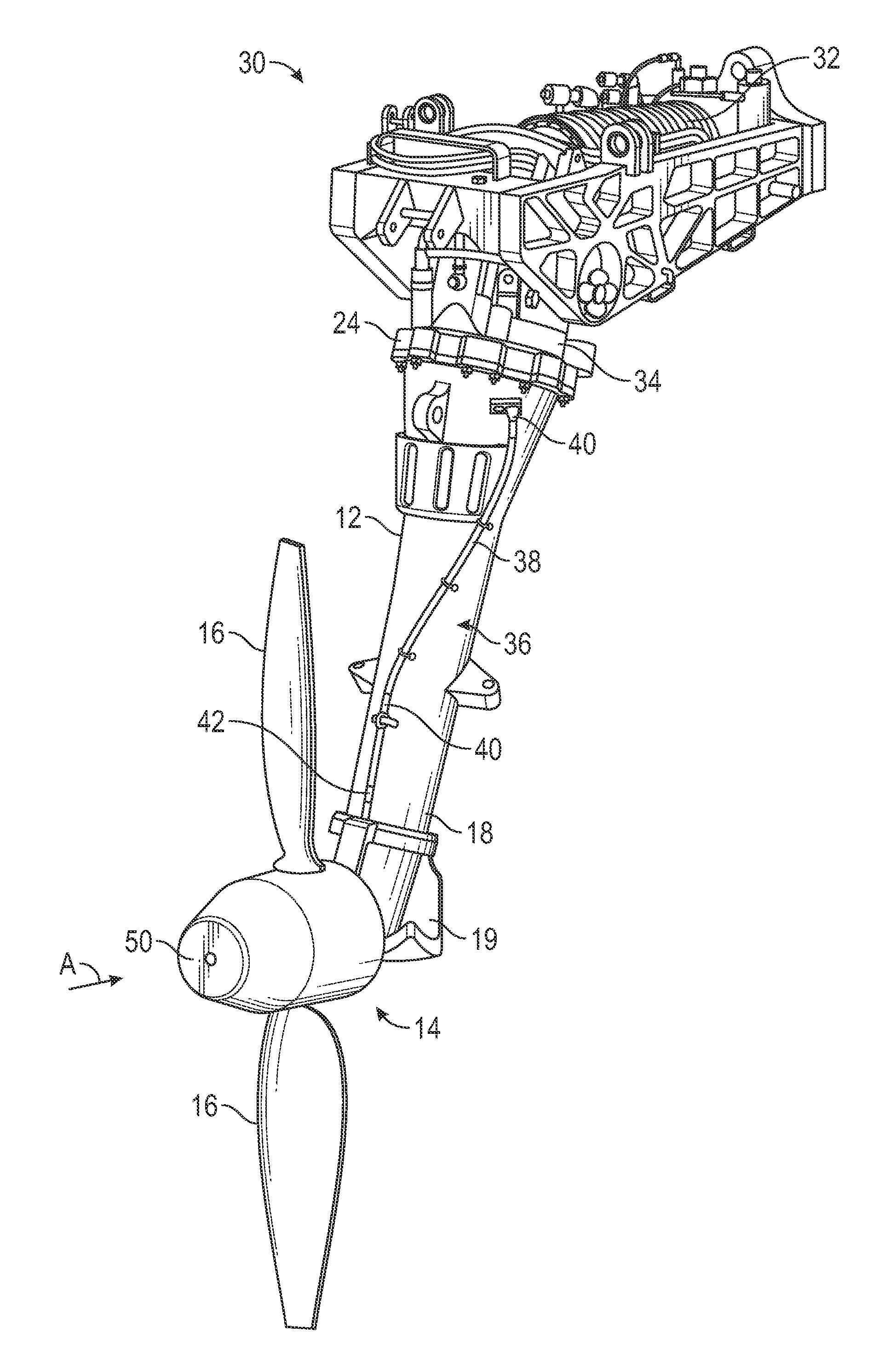
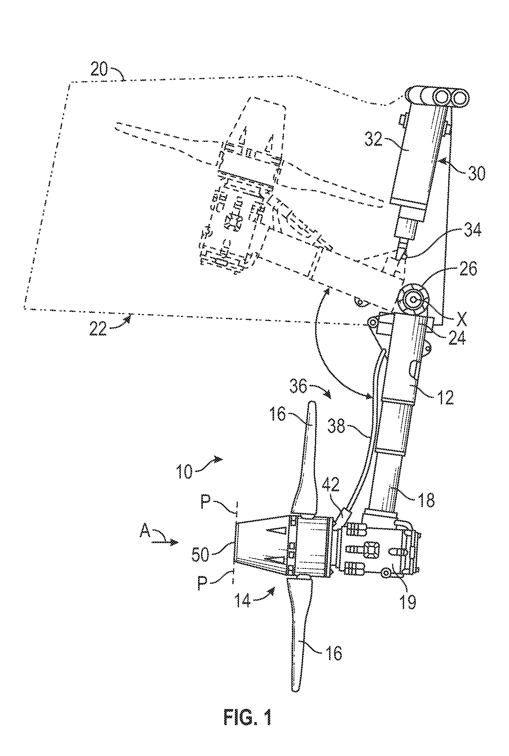
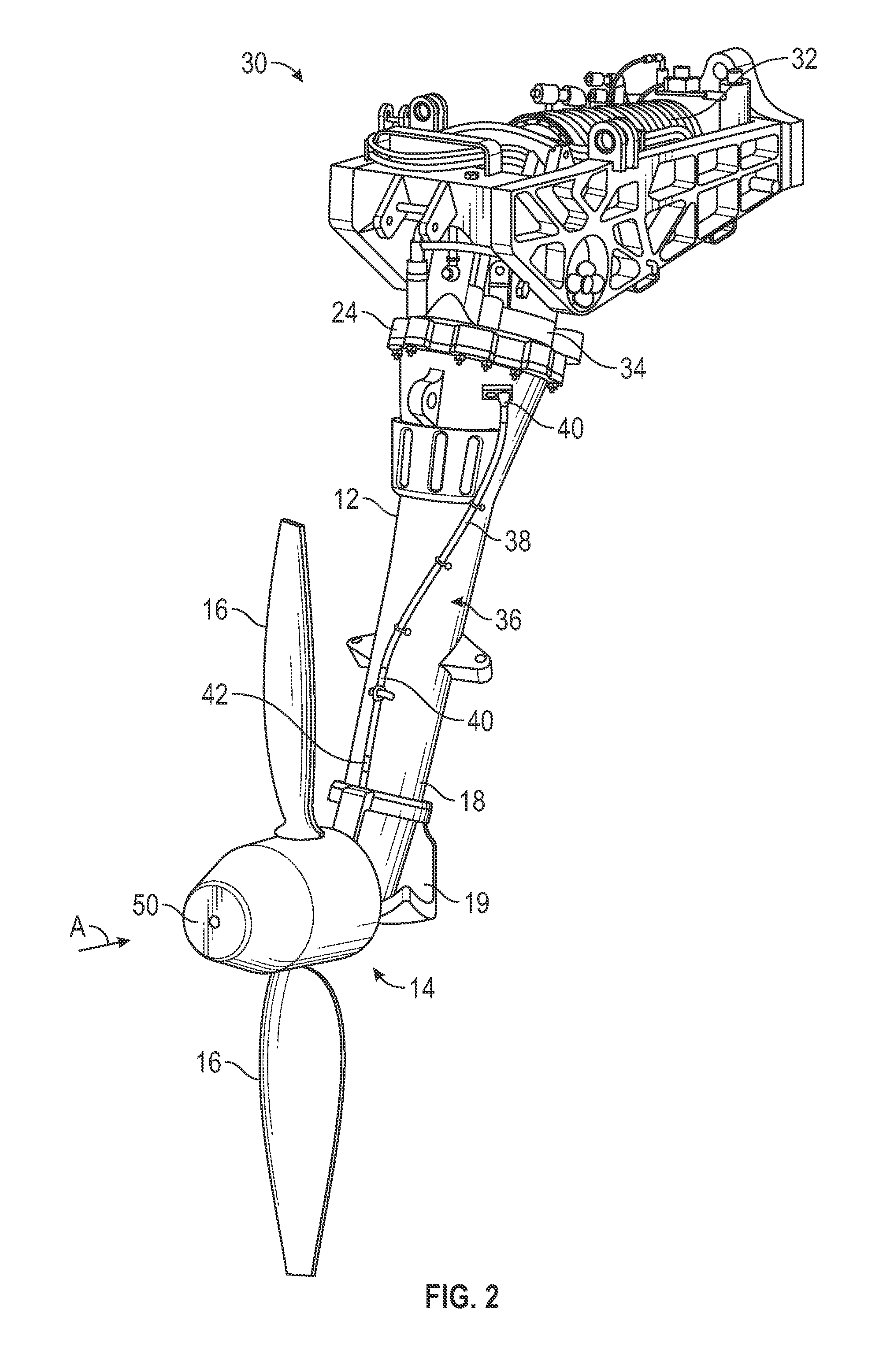
[0012]Referring now to the FIGS. 1 and 2, an exemplary ram air turbine (RAT) 10 having an associated deployment mechanism including a strut 12 is illustrated. The RAT 10 has a rotatable hub assembly 14 with two or more blades 16 configured to impart rotation to the rotatable hub assembly 14 when exposed to an airstream indicated by arrow A. A first end 18 of the strut 12 is attached to a housing 19 which rotatably mounts a drive shaft (not shown) fixed to the rotatable hub assembly 14. Rotation is imparted to the drive shaft when the rotatable hub assembly 14 rotates.

[0013]The RAT 10 is intended for emergency use as a drive for power-generating means and has a stowed, inactive position, illustrated in broken lines, and a deployed, active position, illustrated in solid lines. In the stowed position, the RAT 10 is stowed within a compartment 22 interiorly of an aircraft fuselage 20, with the outline of the both the aircraft fuselage 20 and the compartment 22 being illustrated schemati...


PUM


Abstract

A ram air turbine movable between a stowed position and a deployed position is provided including a rotatable hub assembly. A hub face is arranged at a first end of the rotatable hub assembly. The hub face has a non-planar configuration such that a limited portion of a surface area of the hub face is arranged within a plane oriented perpendicular to a direction of travel of an airflow upstream from the hub face when the ram air turbine is in a deployed position.

Description

BACKGROUND OF THE INVENTION[0001]Exemplary embodiments of this invention generally relate to emergency power supplies for aeronautical applications, and more particularly, to an improved ram air turbine assembly for generating emergency power for an aircraft in flight.[0002]Aircrafts include, as standard equipment, a back-up power source for use in times of power outage in the main power system. The back-up equipment is stowed in a stowage bay within the fuselage or wing root of the aircraft. One example of such back-up equipment is a ram air turbine (RAT). During an emergency event, such as power loss for example, the RAT can be deployed into the airstream where the passing air relative to the speed of the aircraft causes the turbine blades of the back-up equipment to rotate. A RAT may generate hydraulic power, electric power, or both. The turbine is coupled to suitable power generating equipment, such as a hydraulic pump for hydraulic power, or an electric generator for electric p...

Claims


Application Information

Patent Timeline
IPC IPC(8): B64D41/00F01D25/02F01D5/28
CPCB64D41/007F01D25/02F01D5/288F05D2300/43F01D5/025F02C7/047F05D2250/232F05D2300/501F05D2300/512F05D2220/34Y02T50/60B64C11/14F05D2230/90F01D15/10
Inventor BORTOLI, STEPHEN MICHAELFENELON, GEOFFREY D.SEIDEL, WILLIAM E.FAHRNER, ALAN J.GIAMATI, MICHAEL JOHNHOPKINS, GREGORY C.CORCORAN, MARK WALTERRIBAROV, LUBOMIR A.
Owner HAMILTON SUNDSTRAND CORP
Why Eureka
Try Eureka