
Servo valves

a technology of servo valves and valve bodies, which is applied in the direction of plug valves, water supply installation, gas/liquid distribution and storage, etc., can solve the problems of increasing the complexity of servo valves, affecting the cost, reliability and serviceability of valves, and achieves a higher degree of precision

Inactive Publication Date: 2016-05-05
BLAGDON ACTUATION RES
View PDF2 Cites 7 Cited by
  • Summary
  • Abstract
  • Description
  • Claims
  • Application Information

AI Technical Summary

Benefits of technology

The present invention provides a mechanism for controlling a servo valve that allows for tailoring the amount of rotation of the spool required for a particular application. Additionally, the path of the curvilinear groove can be varied to optimize the gearing between the spool and motor without changing the dimensions of the spool and manifold. The design also maximizes the flow for a given control valve size. The spool can be rotated to allow simultaneous bi-directional flow of fluid through the valve. The surface of the spool covers the second fluid outlet when in the first position.

Problems solved by technology

However, such gearing mechanisms increase the complexity of the servo valve and therefore impact upon the cost, reliability and serviceability of the valve.

Method used


Image

  • Servo valves
  • Servo valves
  • Servo valves

Examples


Embodiment Construction

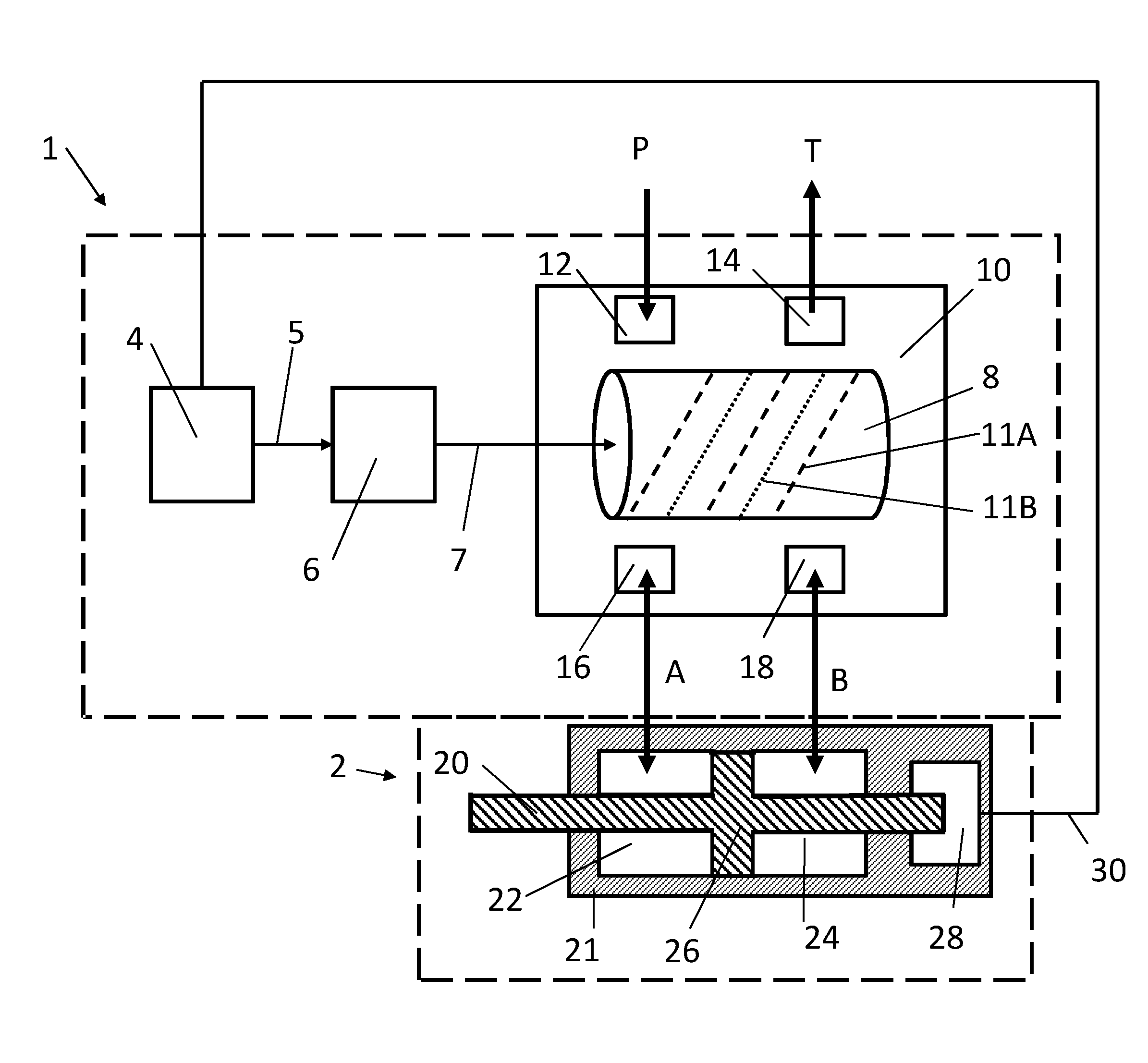
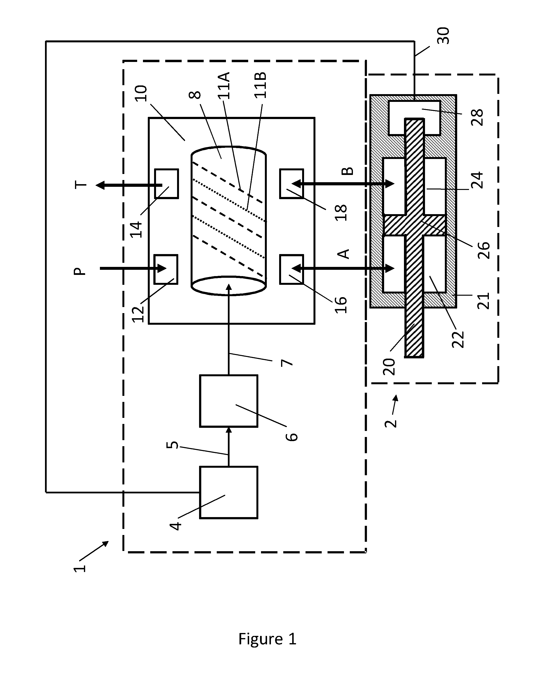
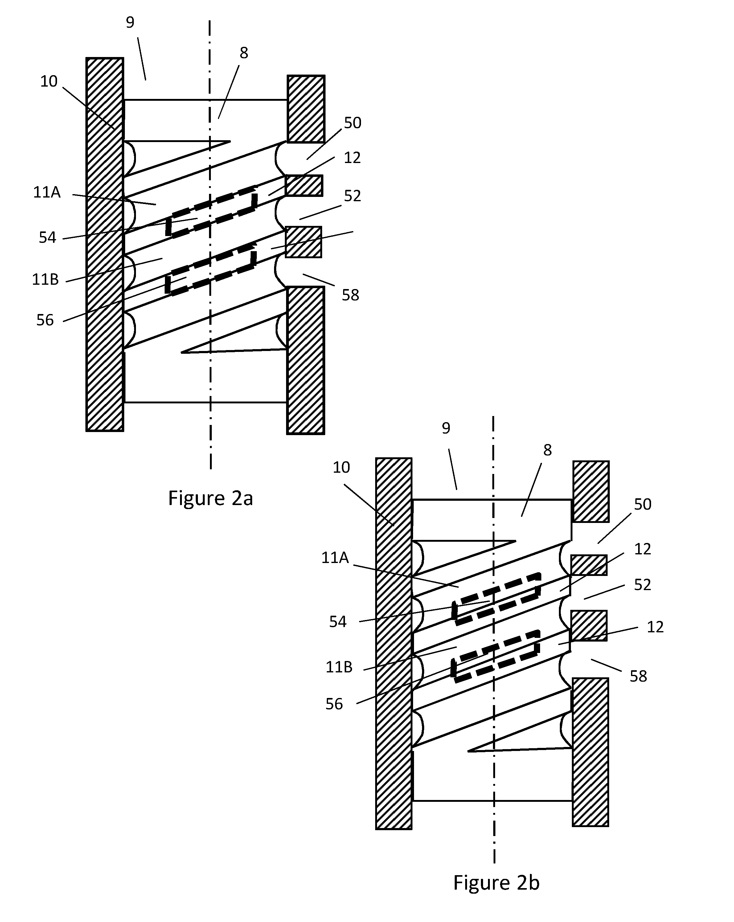
[0071]FIG. 1 shows a schematic view of a servo valve 1 and an actuator 2. The servo valve 1 includes control electronics 4, a motor 6, a spool 8 and a manifold 10. The motor is connected to the control electronics 4 by a signal line 5 and to the spool 8 by a drive shaft 7. The spool 8 is located within a cavity 9 inside the manifold 10 and is mounted for angular rotation about its longitudinal axis. The surface of the spool includes two grooves 11a and 11b (denoted by dashed and dotted lines respectively in FIG. 1). The manifold includes a supply pressure port 12, a tank outlet port 14, a first control port 16 and a second control port 18. The manifold 10 includes one or more flow galleries (not shown) linking the supply pressure port 12, which connects with a pressurised supply P, to the fluid inlet 50 (see FIG. 2) and the tank outlet port 14, which connects with an unpressurised tank T, to the fluid outlet 52 (see FIG. 2). Further flow galleries (not shown) within the manifold 10 ...


PUM


Abstract

A servo valve comprises a fluid inlet, a fluid outlet and a cylindrical spool. The spool has a surface including a curvilinear groove and is mounted for rotational movement between a first position in which the surface of the spool covers at least one of the fluid outlet and the fluid inlet and a second position in which the groove is aligned with the fluid inlet and the fluid outlet.

Description

TECHNICAL FIELD[0001]The present invention concerns improvements in and relating to servo valves. More particularly, this invention concerns an improved spool design for use in a servo valve.BACKGROUND OF THE INVENTION[0002]Servo valves are used in a wide variety of industries to control the movement of hydraulic or pneumatic actuators in response to an input signal and are employed in industries where precise control of an actuator is required, for example in the aerospace industry. Servo valves alter the flow of a fluid through the valve in order to control the position, velocity, acceleration or force generated by an actuator, for example a hydraulic or pneumatic cylinder or motor.[0003]A servo valve typically comprises a moving element (spool) and a fixed element (sleeve). The relative movement of these two elements controls the flow of fluid through the valve in response to a mechanical or electrical input signal.[0004]A servo valve typically comprises a motor which moves the s...

Claims


Application Information

Patent Timeline
Patent Type & Authority Applications(United States)
IPC IPC(8): F15B13/04F15B13/044
CPCF15B13/0444F15B13/0406F15B2211/6336F16K5/0407F16K11/0856F15B13/0401F15B13/0402F15B13/044F16K11/065
Inventor COLLINS, ANDREW JOHN
Owner BLAGDON ACTUATION RES
Learn More