Angular selective light control sheeting and method of making the same

a technology of selective light control and angular structure, applied in the direction of photomechanical treatment, instruments, screening processes, etc., can solve the problems of difficult and/or expensive manufacturing at an industrial scale, certain disadvantages of conventional light control films, etc., and achieve the effect of enhancing the structural characteristics of the formed structur

Inactive Publication Date: 2016-05-05
VASYLYEV SERGIY
View PDF7 Cites 20 Cited by
  • Summary
  • Abstract
  • Description
  • Claims
  • Application Information

AI Technical Summary

Benefits of technology

[0013]According to one embodiment, angular selective light control sheeting is formed from an optically transmissive elastic material that allows for its slitting using a sharp object such as a blade or razor. According to one embodiment, micro-louvers are produced by slitting a surface of the material using one or more blades and introducing an opaque material into the slits. In one embodiment, the material may be stretched to accommodate slitting and / or introducing the opaque material. Once the opaque material is introduced into the slits and optionally cured, the slits may be allowed to close upon themselves to form a monolithic structure. In one embodiment, the structural characteristics of the formed structure are enhanced by including an adhesive material into the opaque material or otherwise fusing the slits using heat or other suitable means.

Problems solved by technology

The conventional light control films may exhibit certain disadvantages and can be relatively difficult and / or expensive to manufacture at an industrial scale.

Method used


Image

  • Angular selective light control sheeting and method of making the same
  • Angular selective light control sheeting and method of making the same
  • Angular selective light control sheeting and method of making the same

Examples


Embodiment Construction

[0025]Referring more specifically to the drawings, for illustrative purposes, the present invention is embodied in the apparatus and method generally shown in the preceding figures. It will be appreciated that the apparatus and method may vary as to configuration and as to details of the parts and / or steps without departing from the basic concepts as disclosed herein. Furthermore, elements represented in one embodiment as taught herein are applicable without limitation to other embodiments taught herein, and in combination with those embodiments and what is known in the art.

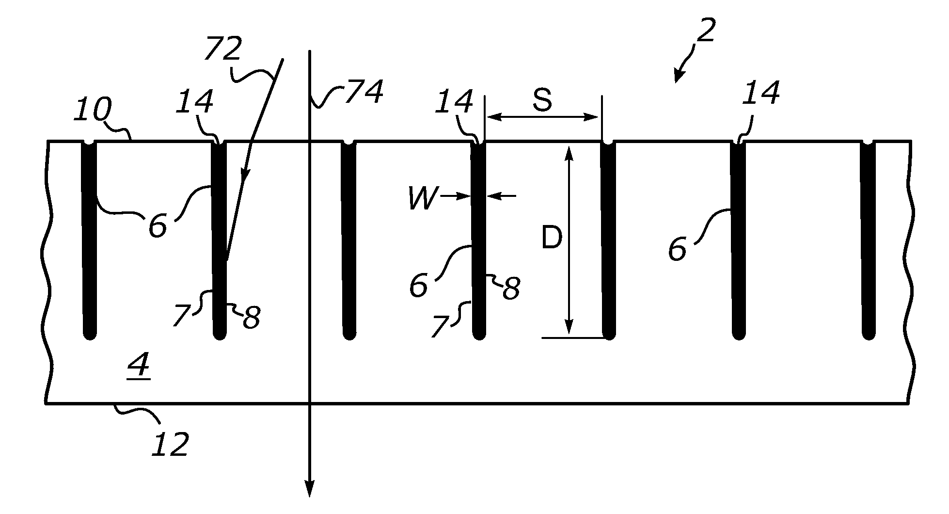
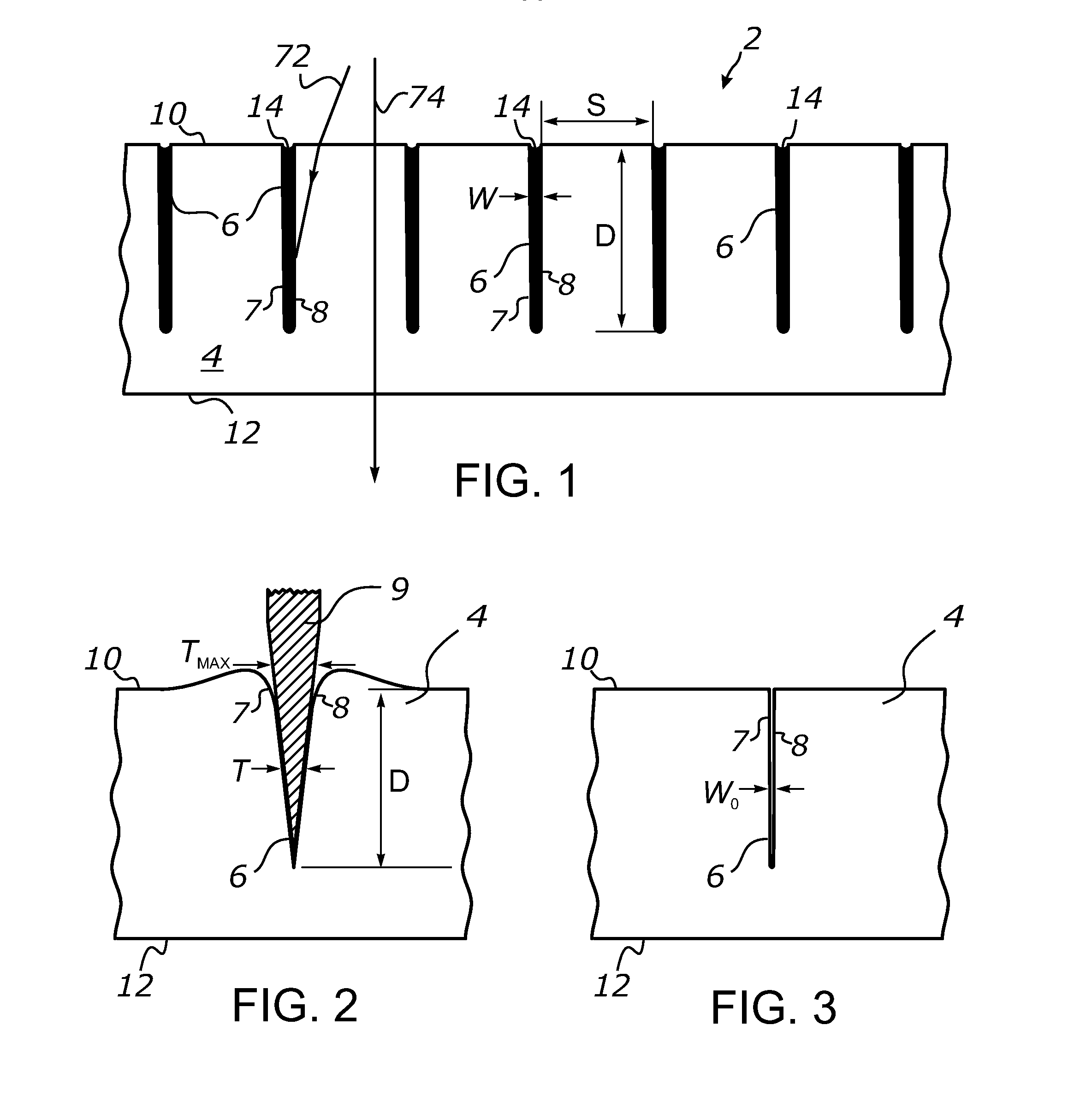
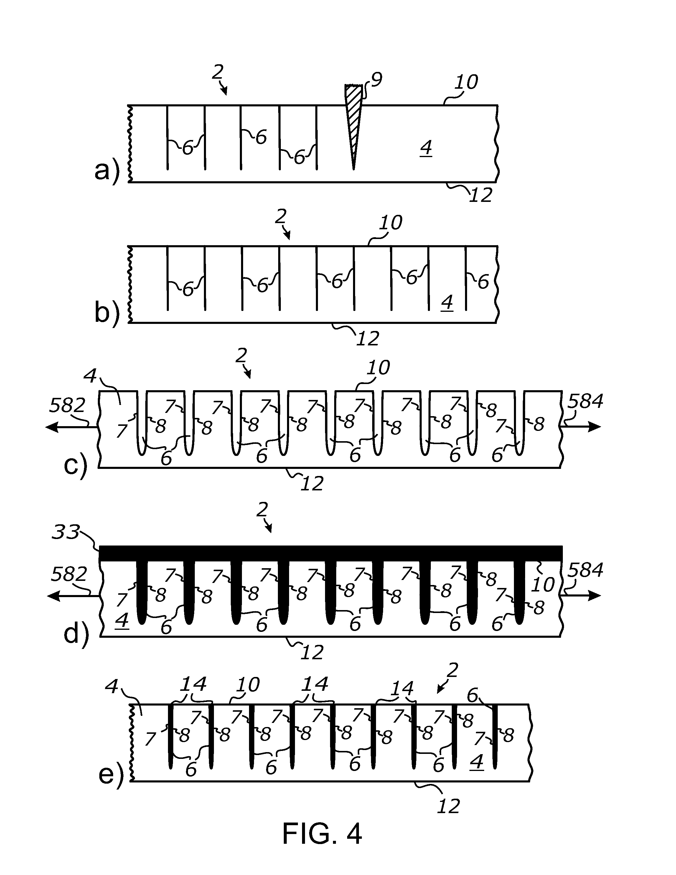
[0026]The present invention particularly seeks to provide angularly selective sheet-form light control materials capable of providing variable transmissivity depending on the angle of incidence and particularly providing high levels of opacity at high incidence angles (generally above about 40 degrees or so).

[0027]The following embodiments of the present invention are generally directed to a sheet-form optical ar...


PUM

PropertyMeasurementUnit
elongation at yieldaaaaaaaaaa
elastic modulusaaaaaaaaaa

Abstract

An angular selective light control sheeting and a method of making the same are disclosed. The light control sheeting includes a layer of an optically clear elastic material which has a series of parallel slits formed by means of surface slitting with a sharp object such as a razor or blade. Each slit is filled with an opaque material which prevents light transmission through the slit walls. The method includes a step of slitting of an elastic, optically transmissive plastic sheet with a blade and forming at least one array of substantially parallel linear slits in a surface of the sheet, a step of stretching the sheet in a direction perpendicular to the linear slits, and a step of introducing an opaque material into the interior of the slits.

Description

CROSS-REFERENCE TO RELATED APPLICATIONS[0001]This application claims priority from U.S. provisional application Ser. No. 62 / 072,283 filed on Oct. 29, 2014, incorporated herein by reference in its entirety.STATEMENT REGARDING FEDERALLY SPONSORED RESEARCH OR DEVELOPMENT[0002]Not ApplicableINCORPORATION-BY-REFERENCE OF MATERIAL SUBMITTED ON A COMPACT DISC[0003]Not ApplicableNOTICE OF MATERIAL SUBJECT TO COPYRIGHT PROTECTION[0004]A portion of the material in this patent document is subject to copyright protection under the copyright laws of the United States and of other countries. The owner of the copyright rights has no objection to the facsimile reproduction by anyone of the patent document or the patent disclosure, as it appears in the United States Patent and Trademark Office publicly available file or records, but otherwise reserves all copyright rights whatsoever. The copyright owner does not hereby waive any of its rights to have this patent document maintained in secrecy, inclu...

Claims


Application Information

Patent Timeline
Patent Type & Authority Applications(United States)
IPC IPC(8): G02B5/00G02B1/04
CPCG02B5/003G02B2207/123G02B1/04
Inventor VASYLYEV, SERGIY
Owner VASYLYEV SERGIY
Why Eureka
Try Eureka