X/hard carbon composite material and method of preparing the x/hard carbon composite material

a composite material and hard carbon technology, applied in the field of hard carbon compositecontaining materials, can solve the problems of not being able to meet the requirements of electrochemical activity, and being considered too expensive for large-scale applications, so as to improve the first specific discharge capacity and avoid the effect of lithium contamination

Active Publication Date: 2018-10-18
FARADION
View PDF2 Cites 9 Cited by
  • Summary
  • Abstract
  • Description
  • Claims
  • Application Information

AI Technical Summary

Benefits of technology

[0030]Another advantage of the present invention is that it is possible to control the particle size of the one or more starting materials which comprise one or more of the component elements of X by for example milling the starting materials; this further assists in the production of uniformly dispersed small particulate X / hard carbon composite.
[0031]The process of the present invention employs a starting material for the hard carbon component of the X / hard carbon composite; the “hard carbon starting material”. Such a hard carbon starting material may be any suitable carbon-containing material which is able to be converted to a hard carbon-containing material either during the process of the present invention, for example during the heating step b), or during a separate carbonization step. Such a suitable carbon-containing material (hard carbon starting material) may include, for example, an organic polymer (e.g. polyacrylonitrile or resorcinol-formaldehyde gel), glucose, sucrose, cellulose etc. The process of the present invention may alternatively employ a hard carbon starting material which already comprises hard carbon, for example because it has been pre-made prior to mixing with the one or more starting materials which comprise one or more of the component elements of X. In other words, the present process can use a hard carbon which is not made in situ as part of the process of the present invention, and as a result, its production does not rely on the in situ carbonization of a hard carbon starting material, Such pre-made hard carbon starting materials are conveniently available from commercial sources such as the Carbotron® hard carbon material (Kureha Corporation), or the Bio-Carbotron™ hard carbon material (Kuraray Chemical Company and Kureha Corporation). Alternatively, a proprietary Faradion hard carbon starting material with particularly advantageous structural characteristics can be easily made in a separate reaction prior to the process of the present invention, starting from a source of carbon such as sucrose-containing, or preferably a carbohydrate-containing material such as corn starch.
[0032]The preferred method to produce the proprietary Faradion pre-made hard carbon starting materials involves firstly heating a carbon source (e.g. sucrose or carbohydrate-containing material) at 220-240° C. for about 24 hours to dry it. Then the sample is ground to a particle size of about 20-30 μm using ball milling apparatus, followed by heating it under an inert atmosphere at a heating rate of about 5° C. / min up to about 1200-1500° C., with a suitable dwell time to effect pyrolysis. Usually the dwell time is 2 hours. The resulting pyrolysed product is then recovered following cooling to room temperature, preferably at a rate of about 5° C. / min.
[0033]Not only are the structural characteristics of a pre-made hard carbon starting material able to be controlled through the choice of carbon source and / or pyrolysis conditions, but its particle size can also be easily modified, for example by milling using suitable apparatus such as a planetary milling machine. Preferably, such pre-made hard carbon-containing starting materials can be milled to a particle size of 1 to 20 μm, preferably from 5 to 15 μm, ideally from 5 to 10 μm, and further ideally from 5 to less than 10 μm.
[0034]The first discharge specific capacity for hard carbon alone is generally under 200 mAh / g, but this value is too low to be of any real commercial value. The Applicant has advantageously found that materials comprising the X / carbon composite made by the present invention which contain at least 5 wt % of component X (as defined above) can significantly improve this first discharge specific capacity. Further, the Applicant has found that when the wt % amount of X in the composite is increased, further improvements in the first specific discharge capacity are also observed.
[0035]The first cycle efficiency is another useful measure of the commercial utility of an anode material. When hard carbon starting materials with a small particle size are used to provide the only source of hard carbon-containing in the anode material the first cycle efficiency is about 80-85%. However, the Applicant has surprisingly found that the materials comprising the X / hard carbon composite made by the process of the present invention show an efficiency over 90% when one or more secondary carbon-containing material is incorporated into the reaction mixture used in the process of the present invention. Preferred secondary carbon-containing materials include any carbon material with a BET nitrogen surface area of at least 5 m2 / g, preferably at least 15 m2 / g, advantageously at least 50 m2 / g, ideally at least 62 m2 / g and further ideally at least 500 m2 / g.

Problems solved by technology

Lithium-ion battery technology has enjoyed a lot of attention in recent years and provides the preferred portable battery for most electronic devices in use today; however lithium is not a cheap metal to source and is considered too expensive for use in large scale applications.
Nevertheless a lot of work has yet to be done before sodium-ion batteries are a commercial reality.
Unfortunately however, graphite is much less electrochemically active towards sodium and this, coupled with the fact that sodium has a significantly larger atomic radius compared with lithium, results in the intercalation between graphene layers in graphite anodes being severely restricted in sodium-ion cells.
Hard carbon has layers, but these are not neatly stacked, and it has micropores (micro-sized pores) formed between the disorderly stacked carbon layers.
One of the reasons why it is difficult to construct a universal structural model of hard carbon is that detailed structures, domain size, fraction of carbon layers and micropores depend on the synthesis conditions, such as carbon sources and carbonization temperatures.
Typical methods of hard carbon production employ starting materials such as sucrose, glucose, petroleum coke or pitch coke, which are mixed with a thermoplastic binder such as coal tar, petroleum based pitch or a synthetic resin, and then heated up to about 1200° C. However, despite being better than graphite, such hard carbon materials only provide a usable capacity in sodium-ion batteries below 300 mAh / g and suffer from slow insertion kinetics and low volumetric energy density.
However, the structural stability of these materials suffer from severe changes in expansion and contraction when Na is inserted and extracted during the charge / discharge process.
However, whilst such a technique allows the nano-particle size of the product to be controlled by varying the milling time and choice of milling media, the process is expected to be expensive to run on a large scale and likely only to be useful for making very small amounts of product, of the order of 5-10 g per batch.
The use of larger quantities of materials is likely to cause serious abrasion to the milling equipment.
Moreover, the HEMM method is known to generate a good degree of heat which will be sufficient to melt low melting metals such as tin, and this will cause handling difficulties.
Therefore, the HEMM process is likely to be uneconomic for commercial anode material production.
Although reasonable percentage cycle life results are reported, it is believed that an anode particle coated with a very thin metallic film will not be very robust and is likely to suffer when the overall particle expands and contracts during charge and discharge.
However, although these processes may lend themselves better to commercial scaling, the formation of hard carbon in situ during a carbonisation process, means that it is difficult to control the nano-metal / hard carbon particle size, and to disperse the metal particles uniformly in the hard carbon matrix.
Further, it has so far not been possible to prepare SnO / hard carbon nano-composite material as attempts to prepare such a material by Shirley Meng et al in the literature discussed above failed, due to the SnO being oxidized to SnO2 during the decomposition of the carbon precursor.
Although the desired outcome of discrete microsperes with well-dispersed, ultra-small Sn particles within a carbon matrix appears to be achieved, this process is complicated and would be expensive to perform, especially on a commercial scale.
The nucleation of the component elements of X onto the carbon surface is not able to occur in the case of the mechanical mixing methods that are employed in some of the prior art where the composite is simply a physical mixture of the components.
The first discharge specific capacity for hard carbon alone is generally under 200 mAh / g, but this value is too low to be of any real commercial value.
The precise temperature used will differ depending on the particular choice of reactants, but it is important that the heating temperature is, on the one hand, high enough to ensure the at least partial reduction of the one or more of the component elements of X in the starting material, and on the other hand is not so high that it encourages the particle size of the components of X in the X / hard carbon composite to grow too large, because this causes problems as discussed below.
If the grain size of X is not controlled within the desired size limits then the resulting X / hard carbon composite is found to exhibit poor electrochemical behaviour when used as an anode material.

Method used


Image

  • X/hard carbon composite material and method of preparing the x/hard carbon composite material
  • X/hard carbon composite material and method of preparing the x/hard carbon composite material
  • X/hard carbon composite material and method of preparing the x/hard carbon composite material

Examples


example 2

[0149]Target composition: 10 wt % Sn, 90 wt % Hard Carbon

[0150]Starting materials: SnO2 and Faradion Hard Carbon (derived from pyrolysed corn starch).

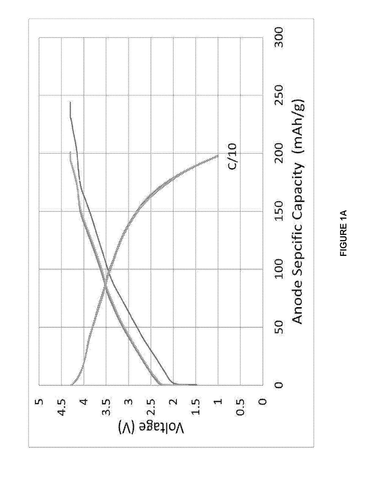
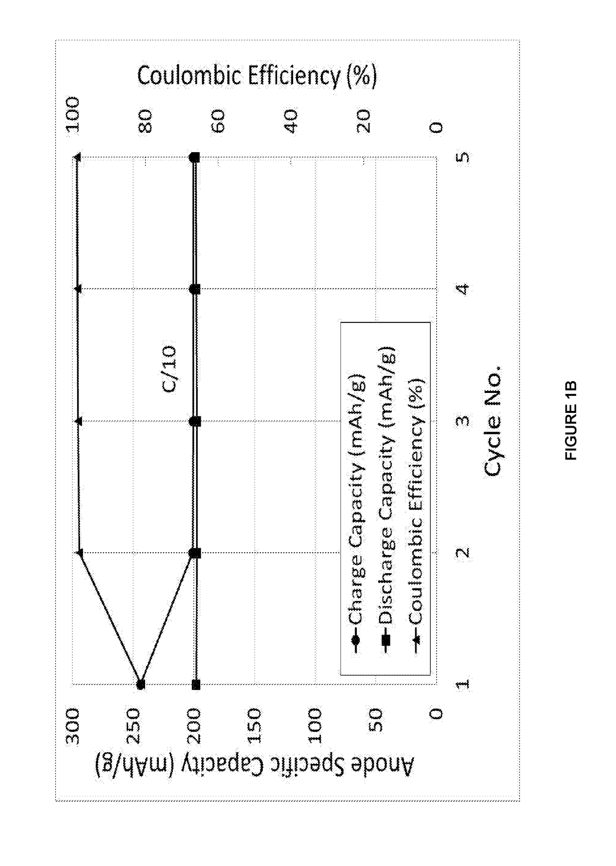
[0151]The data shown in FIGS. 2A, 2B are derived from the constant current cycling data for a Hard Carbon composite (Sn 10 wt %, Hard Carbon 90 wt %) materials in a Na-ion cell where this Anode materials was coupled with the standard cathode material. The electrolyte used is a 0.5 M solution of NaPF6 in propylene carbonate (PC), ethylene carbonate (EC) and diethylcarbonate (DEC) 1:1:2 by weight. The constant current data were collected at an approximate a current rate of C / 10 between voltage limits of 1.00 and 4.30 V. To ensure that the Na-ion cell was fully charged, the cell was potentiostatically held at 4.30 V at the end of the constant current charging process until the current density dropped to 10% of the constant current value. The testing was carried out at 30° C. During the cell charging process, sodium ions are extracted from...

example 3

[0155]Target composition: 30 wt % Sn, 70 wt % Hard Carbon

[0156]Starting materials: SnO2, Faradion Hard Carbon (derived from pyrolysed corn starch.

[0157]The data shown in FIGS. 3A, 3B are derived from the constant current cycling data for a Hard Carbon composite (Sn 30 wt %, Hard Carbon 70 wt %) materials in a Na-ion cell where this Anode materials was coupled with the standard cathode material. The electrolyte used is a 0.5 M solution of NaPF6 in propylene carbonate (PC), ethylene carbonate (EC) and diethylcarbonate (DEC) 1:1:2 by weight. The constant current data were collected at an approximate a current rate of C / 10 between voltage limits of 1.00 and 4.30 V. To ensure that the Na-ion cell was fully charged, the cell was potentiostatically held at 4.30 V at the end of the constant current charging process until the current density dropped to 10% of the constant current value. The testing was carried out at 30° C. During the cell charging process, sodium ions are extracted from the...

example 4

[0161]Target composition: 10 wt % Sb, 90 wt % Hard Carbon

[0162]Starting materials: Sb2O3, Faradion Hard Carbon (derived from pyrolysed corn starch), C65™ carbon as the reductant (secondary carbon material).

[0163]The data shown in FIGS. 4A and 4B are derived from the constant current cycling data for a Hard Carbon composite (Sb 10 wt %, Hard Carbon 90 wt %) materials in a Na-ion cell where this Anode material was coupled with the standard cathode. The electrolyte used is a 0.5 M solution of NaPF6 in propylene carbonate (PC), ethylene carbonate (EC) and diethylcarbonate (DEC) 1:1:2 by weight. The constant current data were collected at an approximate a current rate of C / 10 between voltage limits of 1.00 and 4.30 V. To ensure that the Na-ion cell was fully charged, the cell was potentiostatically held at 4.30 V at the end of the constant current charging process until the current density dropped to 10% of the constant current value. The testing was carried out at 30° C. During the cell...


PUM

PropertyMeasurementUnit
particle sizeaaaaaaaaaa

Abstract

The invention relates to novel material comprising X / hard carbon composite and to a process for their preparation, the process comprising the steps: a) forming a mixture comprising i) one or more hard carbon-starting materials, ii) one or more starting materials which comprise one or more of the component elements of X, and optionally iii) one or more secondary carbon-containing materials; and b) heating the resulting mixture at 100° C. to 1500° C. to yield the material comprising the X / hard carbon composite; wherein X comprises one or more component elements selected from antimony, tin, phosphorus, sulfur, boron, aluminium, gallium, indium, germanium, lead, arsenic, bismuth, titanium, molybdenum, selenium, tellurium, cobalt and nickel and wherein X is present in an amount of at least 5% by weight of the material comprising the X / hard carbon composite.

Description

FIELD OF THE INVENTION[0001]The present invention relates to hard carbon composite-containing materials, to a novel process for making materials comprising hard carbon composite, particularly particulate hard carbon composite, to anode electrodes containing such hard carbon composite-containing materials, and to the use of such anode electrodes in, for example, energy storage devices such as batteries rechargeable batteries, electrochemical devices and electrochromic devices.BACKGROUND OF THE INVENTION[0002]Sodium-ion batteries are analogous in many ways to the lithium-ion batteries that are in common use today; they are both reusable secondary batteries that comprise an anode (negative electrode), a cathode (positive electrode) and an electrolyte material, both are capable of storing energy, and they both charge and discharge via a similar reaction mechanism. When a sodium-ion (or lithium-ion battery) is charging, Na+ (or Li+) ions de-intercalate from the cathode and insert into th...

Claims


Application Information

Patent Timeline
Patent Type & Authority Applications(United States)
IPC IPC(8): H01M4/36H01M4/587H01M4/38H01M10/054B01J13/04
CPCH01M4/366H01M4/587H01M4/387H01M10/054B01J13/04H01M2004/027H01M2004/021H01M4/13H01M4/362H01M10/0525C01P2002/52C01P2002/54C01P2002/72C01P2006/40C01B32/05Y02E60/10
Inventor BARKER, JEREMYLIU, YANG
Owner FARADION
Why Eureka
Try Eureka