LED and LED packaging method thereof

Active Publication Date: 2016-05-05
LEDMAN OPTOELECTRONICS
View PDF7 Cites 4 Cited by
  • Summary
  • Abstract
  • Description
  • Claims
  • Application Information

AI Technical Summary

Benefits of technology

This patent text discusses an LED that increases its visible range. This is achieved by using a special packaging method that increases the angle of the light emitted from the LED. Additionally, the LED chip is placed in a special position inside the packaging, which further enhances the lighting performance. The lighting assembly is also located at the central region of the LED, which improves stability and prevents any detachment from the LED during use. Overall, this special LED provides better performance and stability compared to conventional LEDs.

Problems solved by technology

However, this method requires a re-customized die for the LED display screen, with a relatively high manufacturing cost and mean versatility.

Method used


Image

  • LED and LED packaging method thereof
  • LED and LED packaging method thereof
  • LED and LED packaging method thereof

Examples


Embodiment Construction

[0034]To facilitate an understanding of the disclosure, hereinbelow the disclosure will be described in more fully detail with reference to the accompanying drawings. Preferred embodiments of the disclosure are provided in the accompanying drawings. However, the disclosure may also be implemented in a number of different forms, and thus is not limited to the embodiments described herein. Rather, these embodiments are intended to allow a more thorough understanding of the disclosure.

[0035]It should be noted that, when a component is mentioned to be “fixed” on another component, it may be fixed directly on the another component, or there may be an intermediate component. Similarly, when a component is regarded as “connected” to another component, it may be connected directly to the another component, or there may be an intermediate component. Terms “vertical”, “horizontal”, “left”, “right” and other similar phrases used herein are for illustrated purposes only, and should not be const...


PUM


Abstract

An LED is provided, the LED comprising a lighting assembly and a light bead. The light bead encases the lighting assembly. A cross-section of an upper portion of the light bead is an asymmetric shape with respect to the projection of a normal of the lighting assembly on the cross-section of the upper portion of the light bead, while a cross-section at the lower portion of the light bead perpendicular to the axis is a symmetric shape with respect to the projection of the normal of the lighting assembly on the cross-section at the lower portion of the light bead. The lighting assembly is located at a symcenter of the lower portion of the light bead. The aforementioned LED can increase its visible range, and can ensure an even distribution of the internal stress surrounding the lighting assembly. An LED packaging method is also provided.

Description

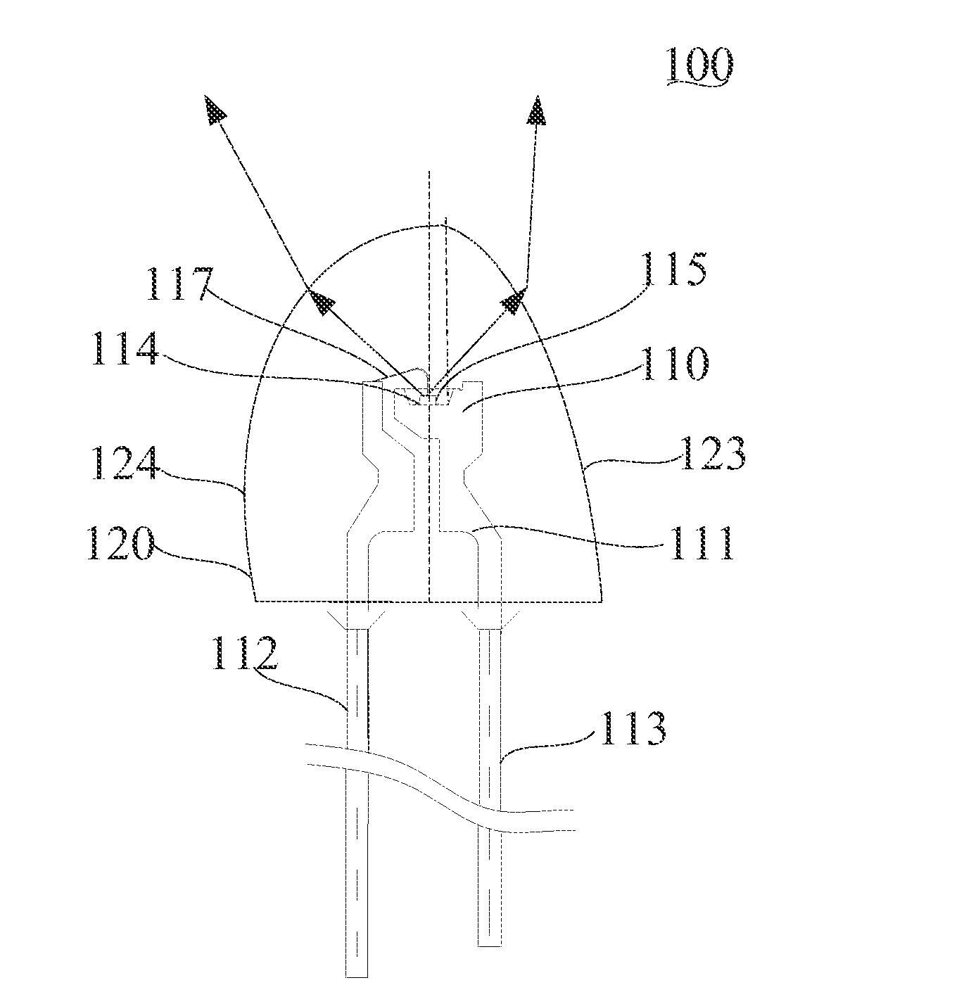
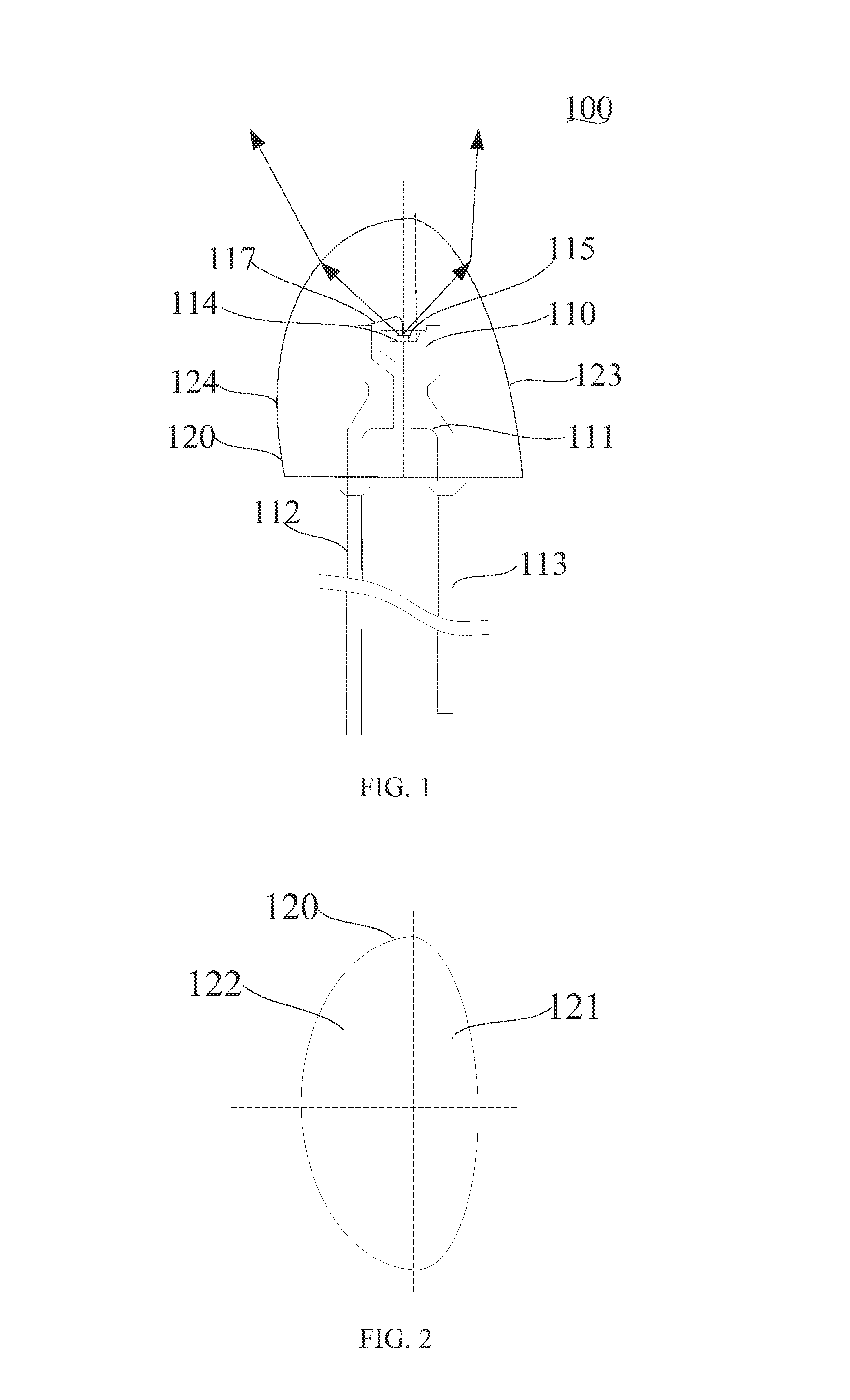
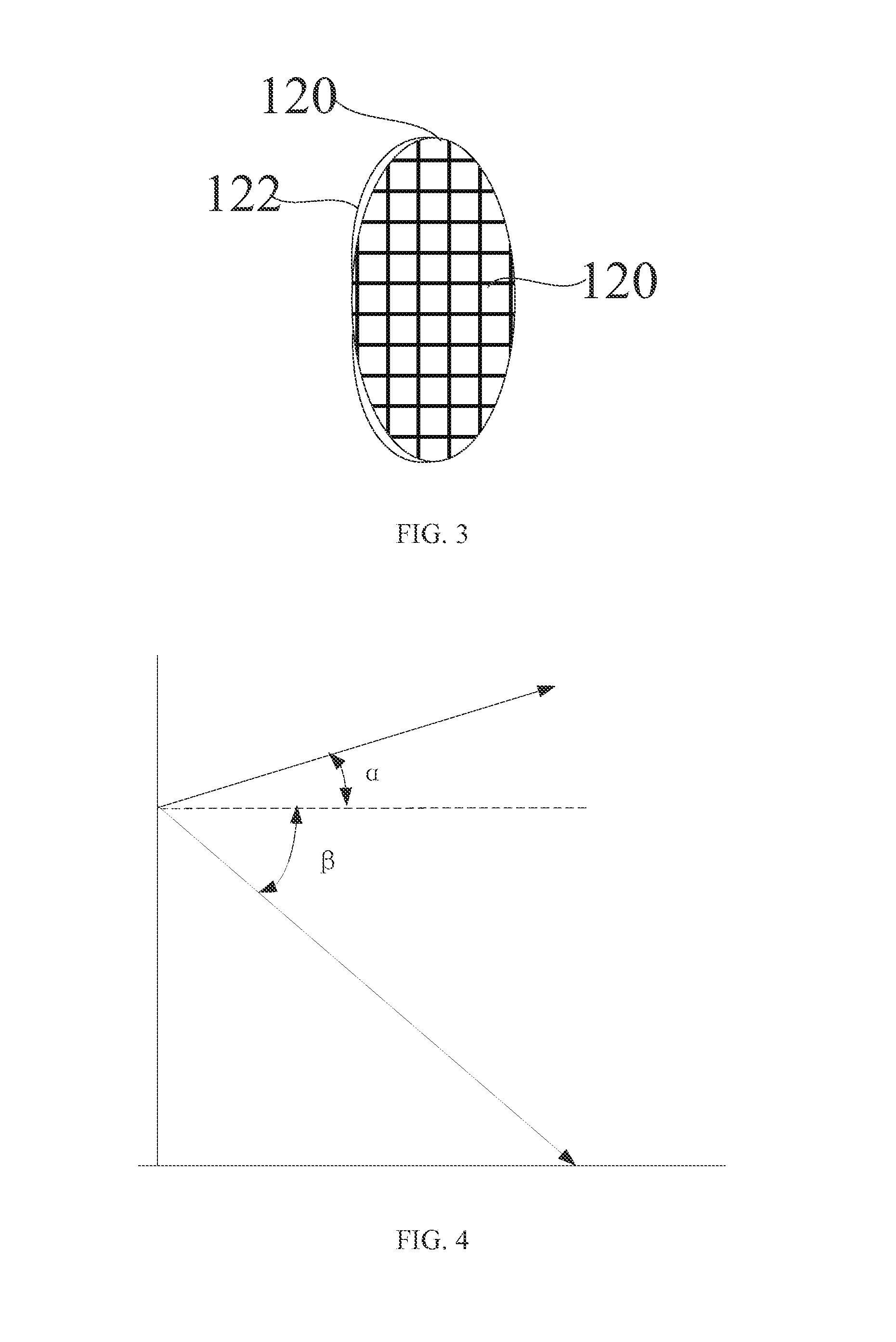
FIELD OF THE DISCLOSURE[0001]The present disclosure relates to a display device, and more particularly, to an LED (light emitting diode) and a packaging method thereof.BACKGROUND OF THE DISCLOSURE[0002]An LED panel is often mounted perpendicular to the horizontal plane, forming an LED display screen. The maximum-brightness view of the LED panel is on its normal direction, and its half-power angle is symmetric with respect to its normal direction. The half-power angle, also known as a power angle, is the angle measured from the normal direction at the center of a light source at which the luminous intensity drops to half the central luminous intensity I, namely I / 2. When the luminous intensity of the light source is evenly distributed, the angles, offset from the normal, at which the surrounding luminous intensities become half the original luminous intensity, should be equal. When the luminous intensity is not even, the angles are not equal. An emitting angle of a diode is its light...

Claims


Application Information

Patent Timeline
IPC IPC(8): H01L33/48H01L33/62
CPCH01L33/483H01L2933/0066H01L2933/0033H01L33/62F21V5/04F21V5/08H01L33/54H01L2224/45144H01L2224/48091H01L2224/48247H01L2924/181H01L2933/005H01L2924/00012H01L2924/00014H01L2924/00
Inventor LI, MANTIETU, MENGLONGXIANG, QIDILIU, HAN
Owner LEDMAN OPTOELECTRONICS
Why Eureka
Try Eureka