
System and method for occupancy sensing using adjustable detection and load control profile

a technology of occupancy sensing and load control, which is applied in the direction of computer control, process and machine control, instruments, etc., can solve the problems of pir occupancy sensors being less able to distinguish the heat signature of a human body from the background heat signature of the surrounding environment, and unable to accurately detect the temperature produced by a human body or an automobile within a wide range of ambient temperature, so as to maximize the own performance and optimize the operation of a lighting system

Active Publication Date: 2016-05-05
LEVITON MFG
View PDF6 Cites 14 Cited by
  • Summary
  • Abstract
  • Description
  • Claims
  • Application Information

AI Technical Summary

Benefits of technology

The patent introduces a sensor that adjusts its sensitivity based on the environment it is placed in. This can be ambient temperature or the time of day. This allows the sensor to perform its best and optimize the operation of the lighting system based on its surroundings.

Problems solved by technology

Although PIR occupancy sensors have also been used in outdoor applications, the ability to accurately detect the temperature produced by a human body or an automobile within a wide range of ambient temperatures is made more difficult.
One reason for this, is because as the ambient temperature of a monitored area rises, the difference between human body temperature and the ambient temperature decreases, and as a result PIR occupancy sensors can be less able to differentiate the heat signature of a human body from the background heat signature of the surroundings.
In addition, detection problems increase when road or parking surface temperatures rise, making it even more difficult for the PIR occupancy sensor to discern the heat signature of a moving object from the background heat signature of the road or parking surface.
Prior occupancy sensing systems also suffer from deficiencies in that they do not adequately take into account time of day.
More particularly, prior outdoor occupancy sensing systems have thus far not had the capability to customize operation based on time of day so as to provide optimum energy savings during periods when low activity is expected.

Method used


Image

  • System and method for occupancy sensing using adjustable detection and load control profile
  • System and method for occupancy sensing using adjustable detection and load control profile
  • System and method for occupancy sensing using adjustable detection and load control profile

Examples


Embodiment Construction

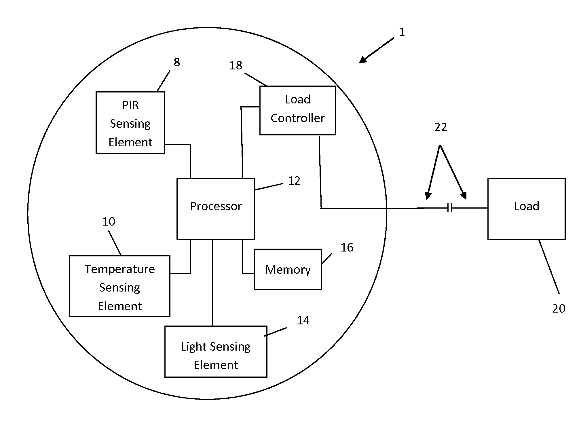
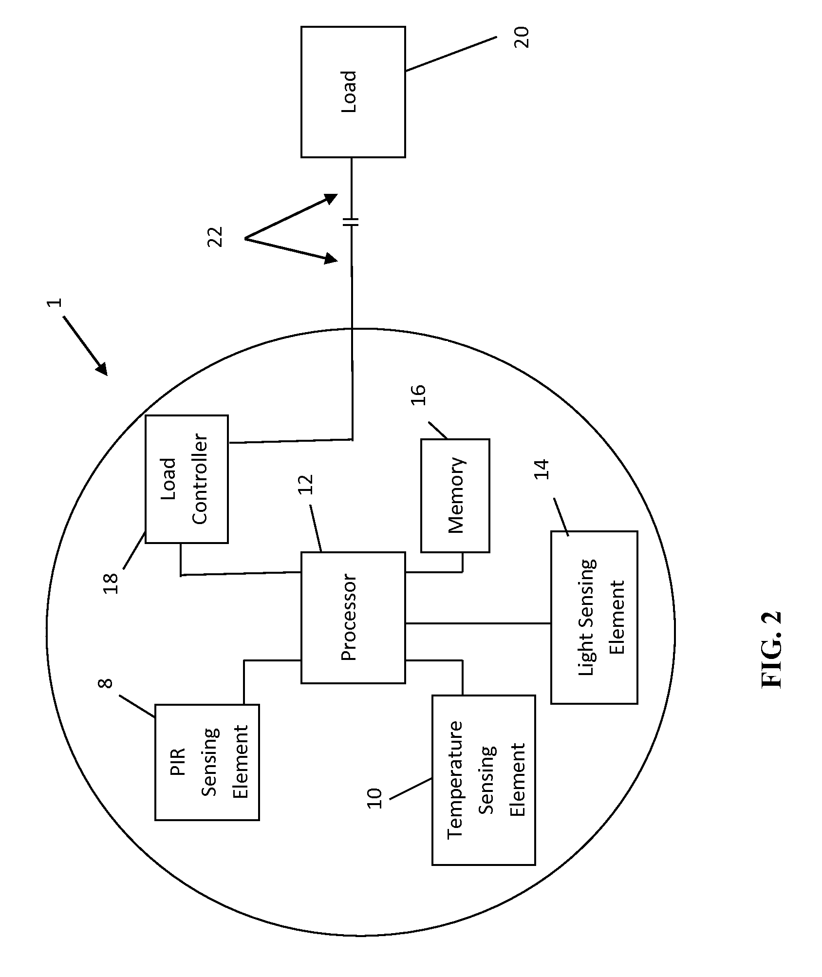
[0017]The disclosed system and method may find use in lighting control systems, which, in some embodiments, are outdoor lighting control systems. In exemplary embodiments, a PIR occupancy sensor can be fine-tuned for best performance by modifying the pre-processing and / or post-processing of a signal from a PIR sensing element in response to changes in ambient temperature. In other embodiments, an occupancy sensor can sense changes in daylight that occur near sunset and sunrise in order to estimate a close approximation of time of day, and can use this estimation to vary operational parameters of the occupancy sensor. Non-limiting examples of operational parameters include, but are not limited to, time delay before turning off an associated load and sensitivity adjustment thresholds.

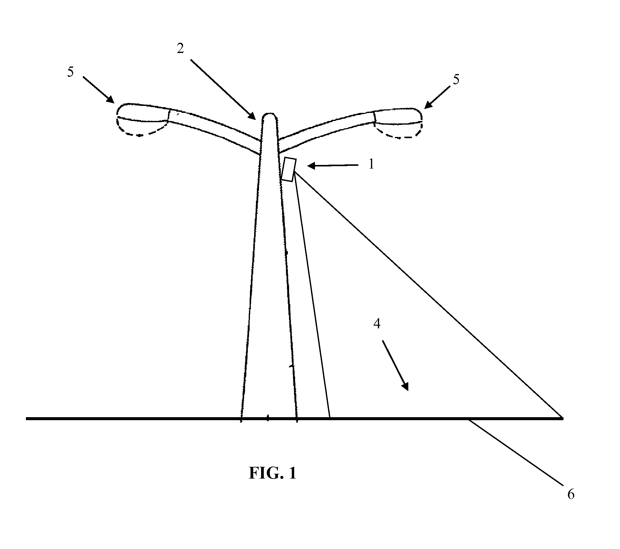
[0018]FIG. 1 shows an exemplary outdoor application in which an occupancy sensor 1 is mounted on an upper region of a light pole 2 so that the sensor can monitor a portion 4 of a parking lot 6 illuminated...


PUM


Abstract

An occupancy sensor is disclosed including a passive infrared (PIR) sensing element, a temperature sensing element, and a processor. The processor receives temperature signals from the temperature sensing element and configures the occupancy sensor into a selected operating mode based the received temperature signal. The operating mode may be associated with a predetermined sensing threshold of the PIR sensing element. The processor controls an associated load based on the selected operating mode and the received occupancy signals. The occupancy sensor can alternatively include an occupancy sensing element and a photodetector. Based on the amount of light detected by the photodetector over time, the occupancy sensor can calculate a rough estimate of time of day, and can automatically adjust one or more sensing and / or operational characteristics based on that time of day determination. A photosensor may implement daylight harvesting based on different light levels associated with different times of day.

Description

FIELD OF THE DISCLOSURE[0001]The present disclosure relates generally to occupancy sensing systems, and more particularly to an improved system and method for occupancy sensing systems having adjustable detection profiles.BACKGROUND OF THE DISCLOSURE[0002]Occupancy sensors are designed to save energy by detecting the presence of a moving object in an area of coverage and switching a load (e.g., a light source, an HVAC system, etc.) on and off depending upon the presence of the moving object. For example, when motion is detected within the area of coverage, the load is turned on. Alternatively, when motion is not detected within the area of coverage, thus indicating that the area of coverage is not occupied, the load is turned off after a predetermined period of time. Occupancy sensors thus facilitate electrical energy savings by automating the functions of, for example, a light switch.[0003]Occupancy sensors using passive infrared detection (PIR) have been employed in a variety of i...

Claims


Application Information

Patent Timeline
Patent Type & Authority Applications(United States)
IPC IPC(8): H02J3/00G05B15/02
CPCG05B15/02H02J3/005H05B47/11H05B47/13Y02B20/40
Inventor HICK, ROBERT L.LEINEN, RICHARD A.
Owner LEVITON MFG
Learn More