Sole member of footwear

a technology of sole member and shoe, which is applied in the direction of sole, footwear, apparel, etc., can solve the problems of leakage of liquid from the joint between the base plate and the cover, and achieve the effect of avoiding the confinement of liquid in the gap and reducing the increase in the pressure resulting from the confinemen

Inactive Publication Date: 2016-05-12
HIMIKO
View PDF11 Cites 2 Cited by
  • Summary
  • Abstract
  • Description
  • Claims
  • Application Information

AI Technical Summary

Benefits of technology

[0060]That is, through employment of dual partition such that one partition is formed in such a manner as to rise from the bottom plate, whereas the other partition is formed in such a manner as to be suspended from the cover, even though, as a result of movement of liquid, a clearance is formed between the upper end of the partition and the lower surface of the cover, liquid which passes through a clearance which opens at the upper end of the inner partition is blocked by the base of the outer partition, so that there can be avoided direct impingement of liquid on the joint located externally of the outer partition.
[0061]Also, by virtue of provision of the grooves or cuts in the first and second partitions, liquid which flows into the gap between the outer partition and the inner periphery of the joint is easily released, through the grooves or cuts, to the inside of the first and second partitions, thereby avoiding confinement of liquid in the gap; thus, an increase in pressure resulting from the confinement can be restrained.
[0062]Furthermore, by means of the grooves or cuts formed in the first partition and the grooves or cuts formed in the second partition being disposed in such a manner as not to overlap each other as viewed from a direction along center lines of the grooves or cuts, there can be avoided an incident in which liquid that flows out from both sides of gaps between the blades as a result of press impinges directly on the joint between the base plate and the cover through the grooves or cuts.

Problems solved by technology

However, despite of employment of the above-mentioned means for preventing leakage of liquid, leakage of liquid from the joint between the base plate and the cover has occurred.

Method used


Image

  • Sole member of footwear
  • Sole member of footwear
  • Sole member of footwear

Examples


Embodiment Construction

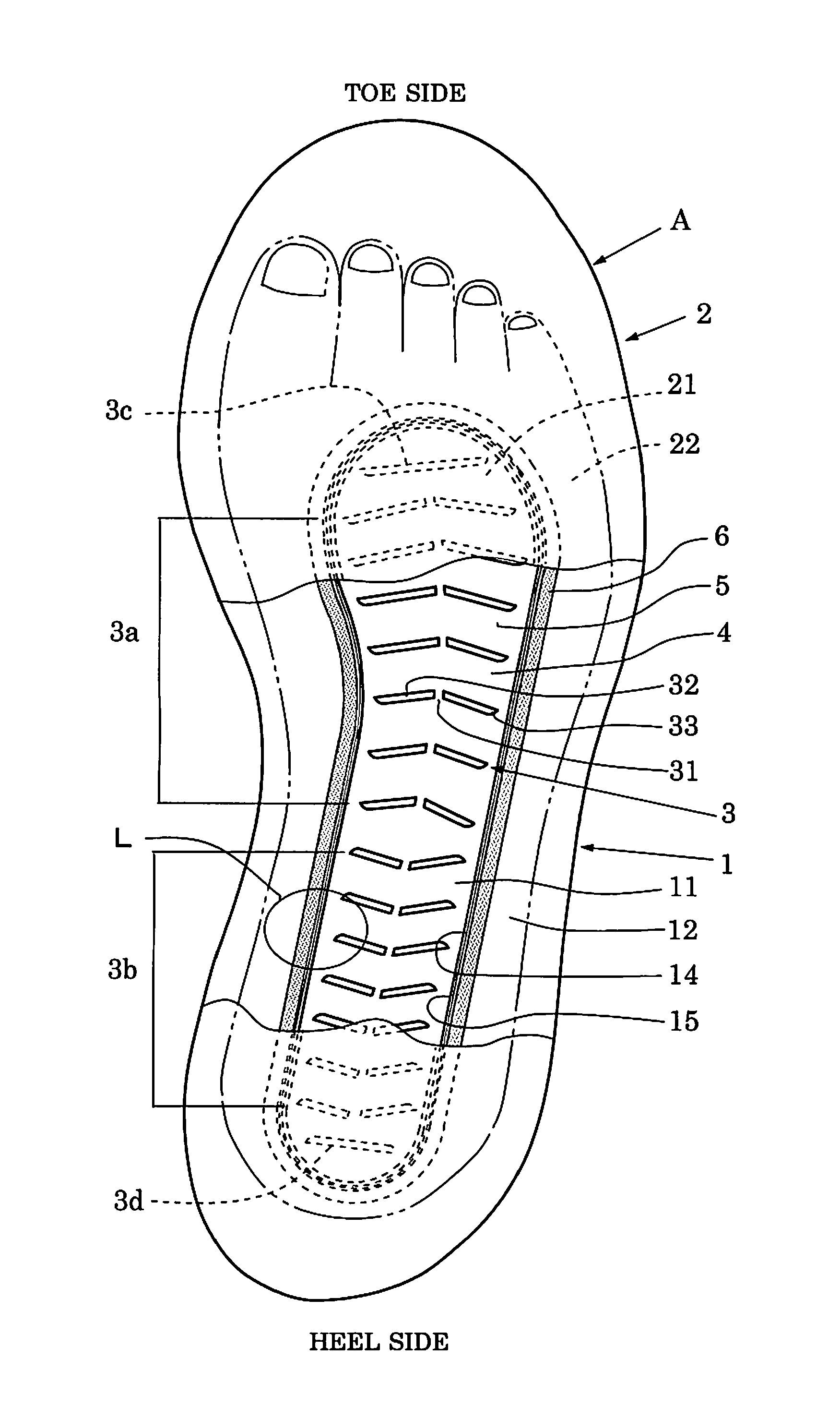
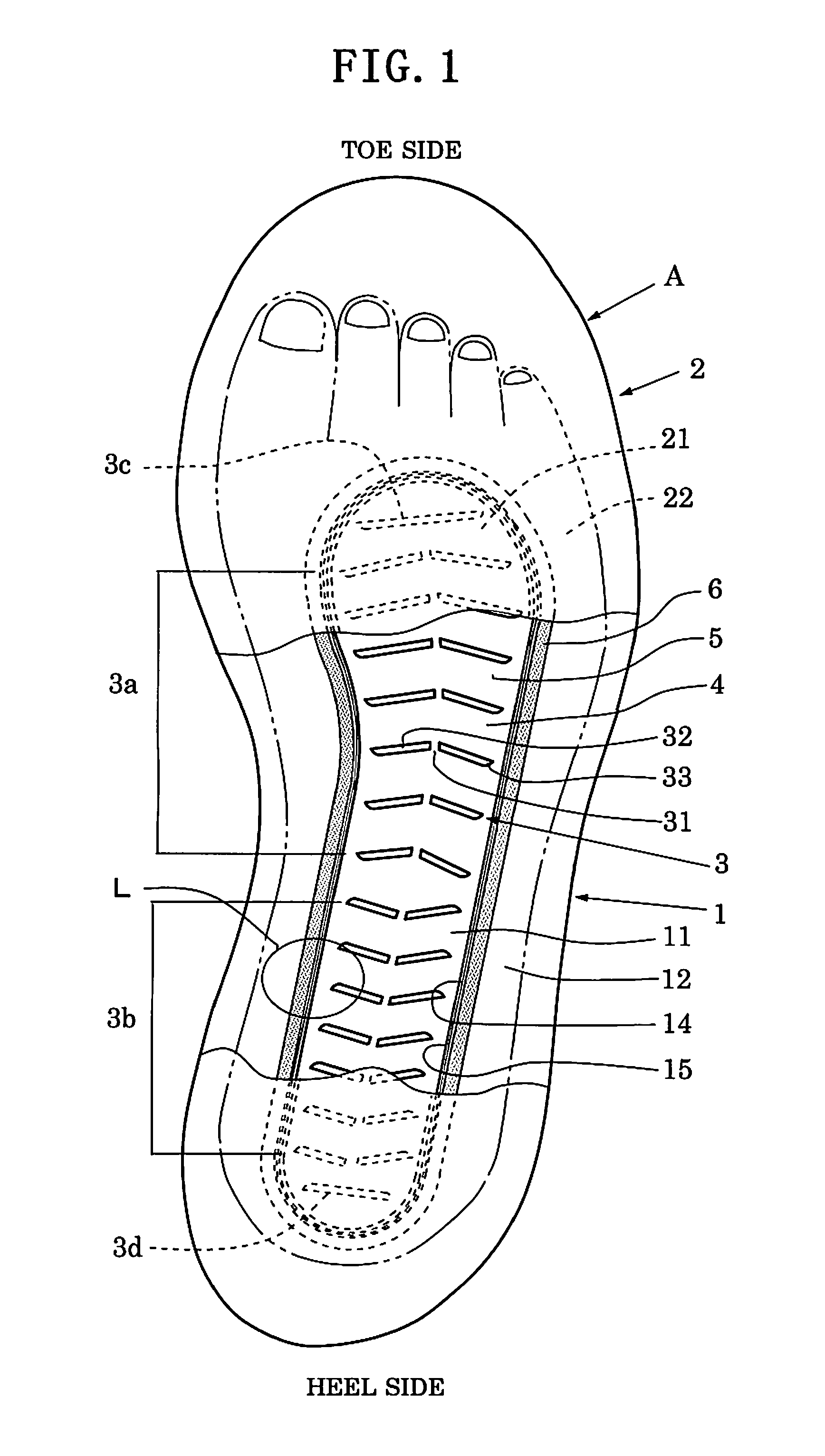
[0097]A sole member of footwear according to the present invention will next be described while referring to a shoe midsole, with reference to FIGS. 1 to 7. As shown in FIG. 1, the shoe midsole A according to the present invention includes a base plate 1, a cover 2, a plurality of blades 3, and liquid 4.

[0098]The base plate 1 has a first region 11 having a shape equivalent to a foot sole, and a first horizontal flange portion 12 surrounding the entire periphery of the first region. The cover 2 has a second region 21 which faces the first region 11 of the base plate 1, and a second horizontal flange portion 22 which faces the first horizontal flange portion 12. As is apparent from FIG. 1, the first region 11 of the base plate 1 has a length extending from the heel to the portion near to the roots of the toes, and a width of the portion where foot sole contacts with, when foot sole touches down on the ground.

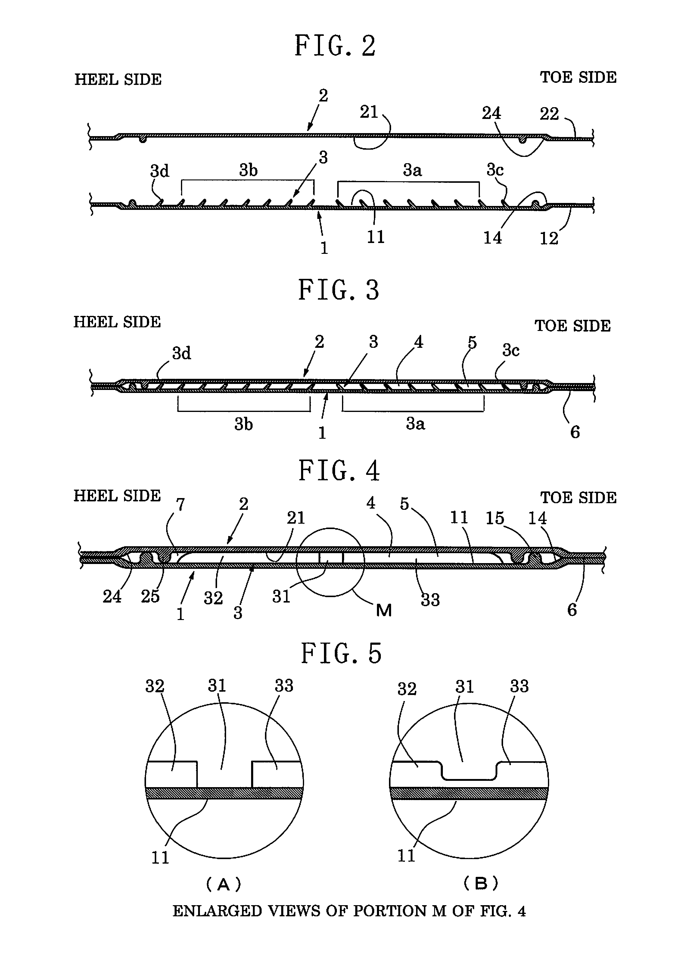
[0099]As shown in FIGS. 2 to 4, the first region 11 has a concave shape which...


PUM


Abstract

A shoe midsole is composed of a base plate (1), a cover (2), a plurality of blades (3), and liquid (4). The blades (3) are formed in such a manner as to rise within a first region (11) of the base plate (1). The blades (3) are each composed of a plurality of flat-shaped blade elements (32, 33) separated each other by slits (31), and are tilted toward the toe side or the heel side. The flat-shaped blade elements (32, 33) are disposed in such a manner as to be divergent toward the toe side or the heel side. The base plate (1) and the cover (2) are joined together, thereby forming a closed space (5), and the liquid (4) is sealed in the closed space.

Description

TECHNICAL FIELD[0001]The present invention relates to a sole member of footwear, and more particularly to a sole member of footwear which absorbs impact during walking while providing feeling of stable, comfortable walking, exhibits a massaging effect through stimulation of the foot sole, and can prevent leakage of liquid sealed therein.BACKGROUND ART[0002]When the heel touches down on the ground, impact force imposed on the heel is said to be about 1.25 times the body weight during walking and about three times during jogging. The impact is transmitted to the heel, the ankle, the knee, and then the waist and imposes loads on these regions. Also, it has been known that, as compared with impact applied when the heel touches down on the ground, impact applied when the toes kick the ground is greater.[0003]Thus, the inventors of the present invention have proposed a shoe insole which disperses and absorbs impact applied to the foot sole when the foot sole lands on the ground during wal...

Claims


Application Information

Patent Timeline
Patent Type & Authority Applications(United States)
IPC IPC(8): A43B13/18A43B17/02
CPCA43B13/181A43B17/026A43B13/189A43B13/40A43B7/144A43B7/1445A43B13/127A43B13/386
Inventor SHIBATA, OSAMUSHIBATA, MASAO
Owner HIMIKO
Why Eureka
Try Eureka