Centrifugal compressor and turbocharger

a centrifugal compressor and turbocharger technology, which is applied in the direction of machines/engines, mechanical equipment, liquid fuel engines, etc., can solve the problems of large change in pressure or flow rate of fluid, surges, and disturb the main flow, so as to improve quietness and suppress surges

Active Publication Date: 2016-05-12
IHI CORP
View PDF12 Cites 8 Cited by
  • Summary
  • Abstract
  • Description
  • Claims
  • Application Information

AI Technical Summary

Benefits of technology

[0017]According to the present disclosure, it is possible to improve quietness while suppressing surges by providing a return flow passage.

Problems solved by technology

This leads to a large change in pressure or the flow rate of fluid, which may cause noises (so-called surges).
Thus, the circulated air interferes with the main flow, which possibly disturbs the main flow.
Depending on operational conditions, this disturbance of the main flow may cause a large noise in association with the flow of air, which possibly leads to deterioration in quietness.

Method used


Image

  • Centrifugal compressor and turbocharger
  • Centrifugal compressor and turbocharger
  • Centrifugal compressor and turbocharger

Examples


Embodiment Construction

[0023]Hereinbelow, an embodiment of the present disclosure will be described in detail with reference to the attached drawings. Dimensions, materials, specific numbers, and other items described in the embodiment are merely examples for facilitating understanding of the invention. Thus, these pieces of information do not restrict the present invention. Note that, in this specification and the drawings, the same reference signs are attached to elements having substantially the same function or configuration, and explanation thereof will not be repeated. Furthermore, elements that are irrelevant to the present disclosure are not illustrated.

[0024]In the following embodiment, description will be made of a turbocharger including a centrifugal compressor as an example. Schematic configuration of the turbocharger will be first described, and then, details of the configuration of the centrifugal compressor of the turbocharger will be described.

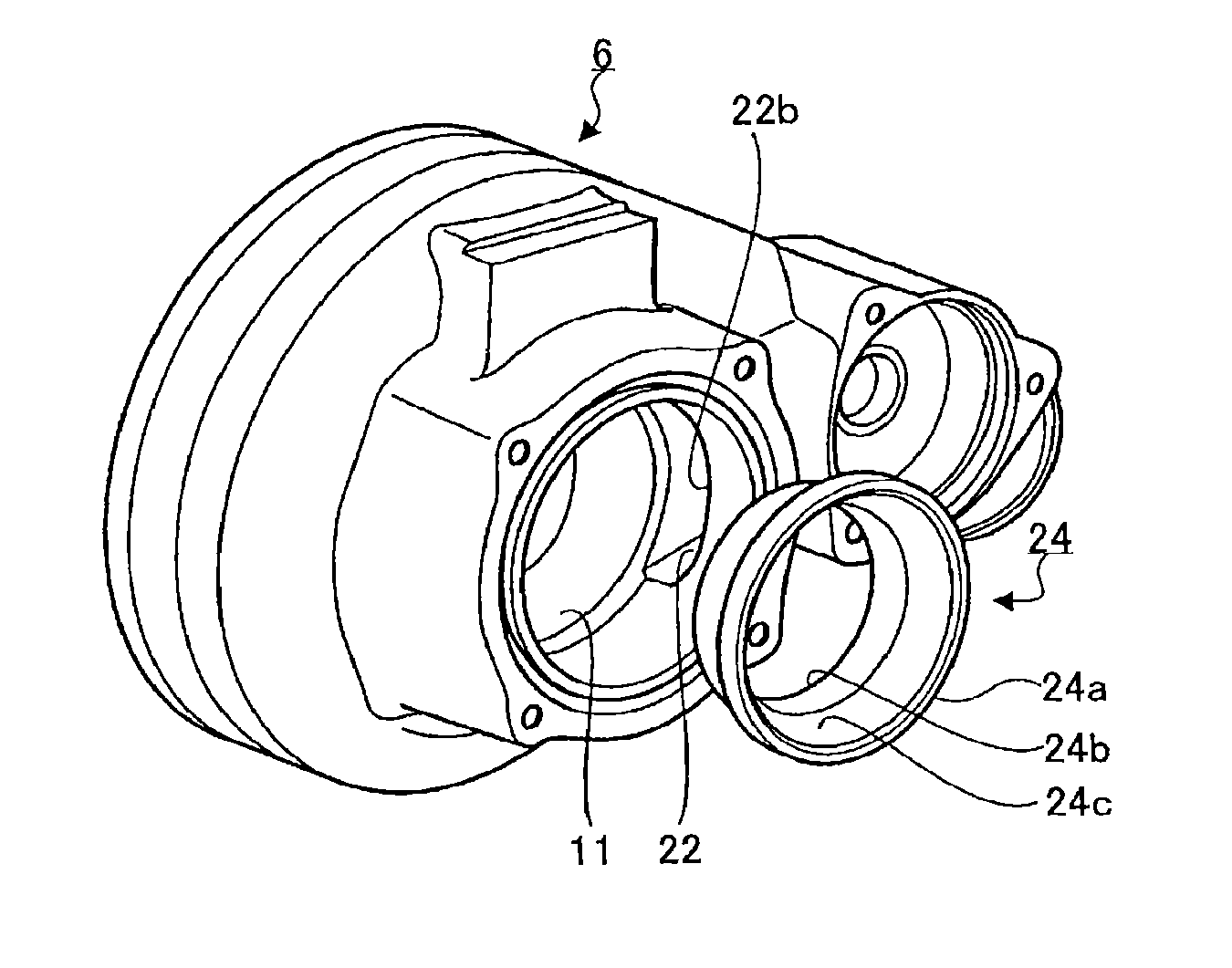
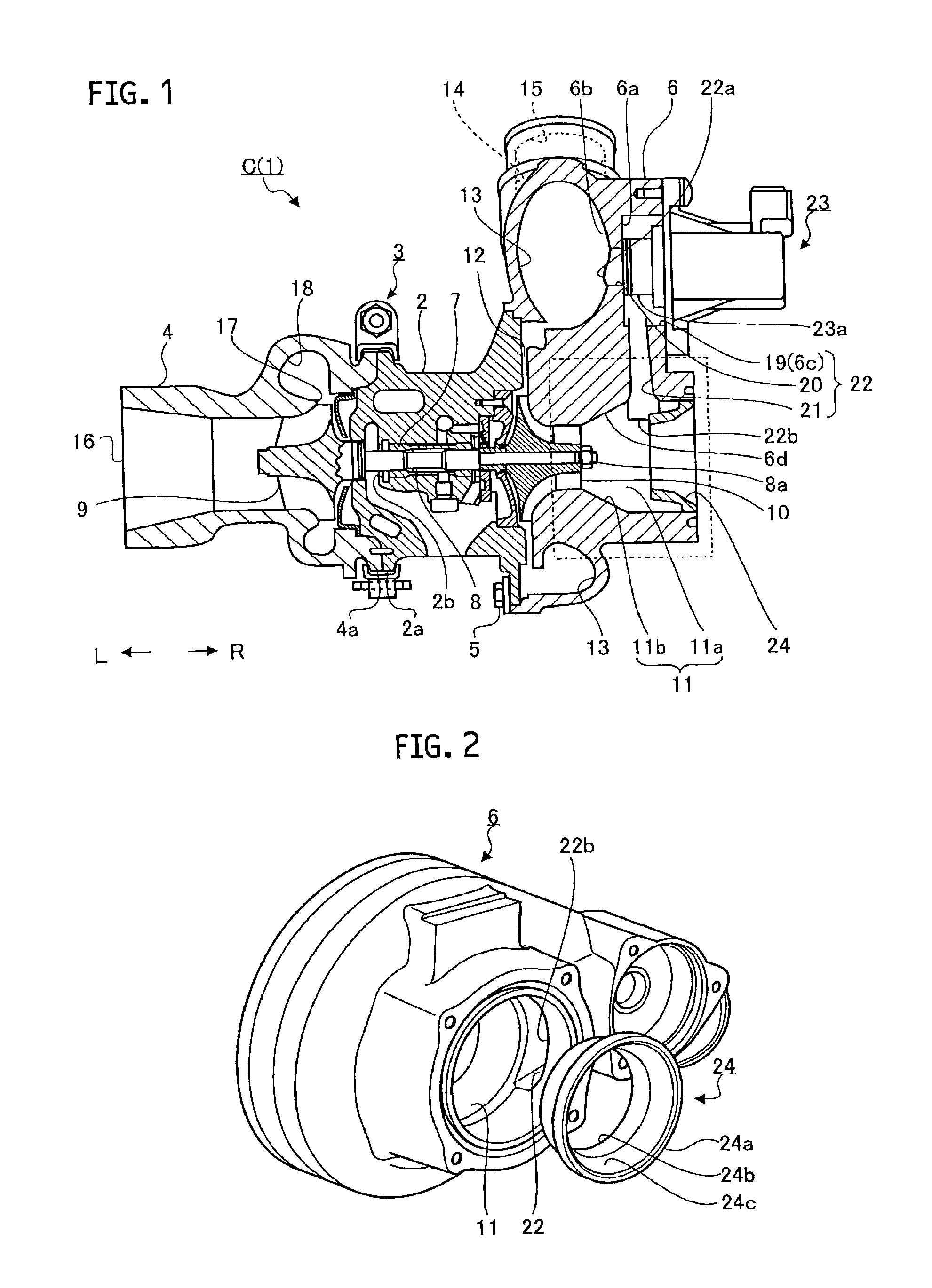
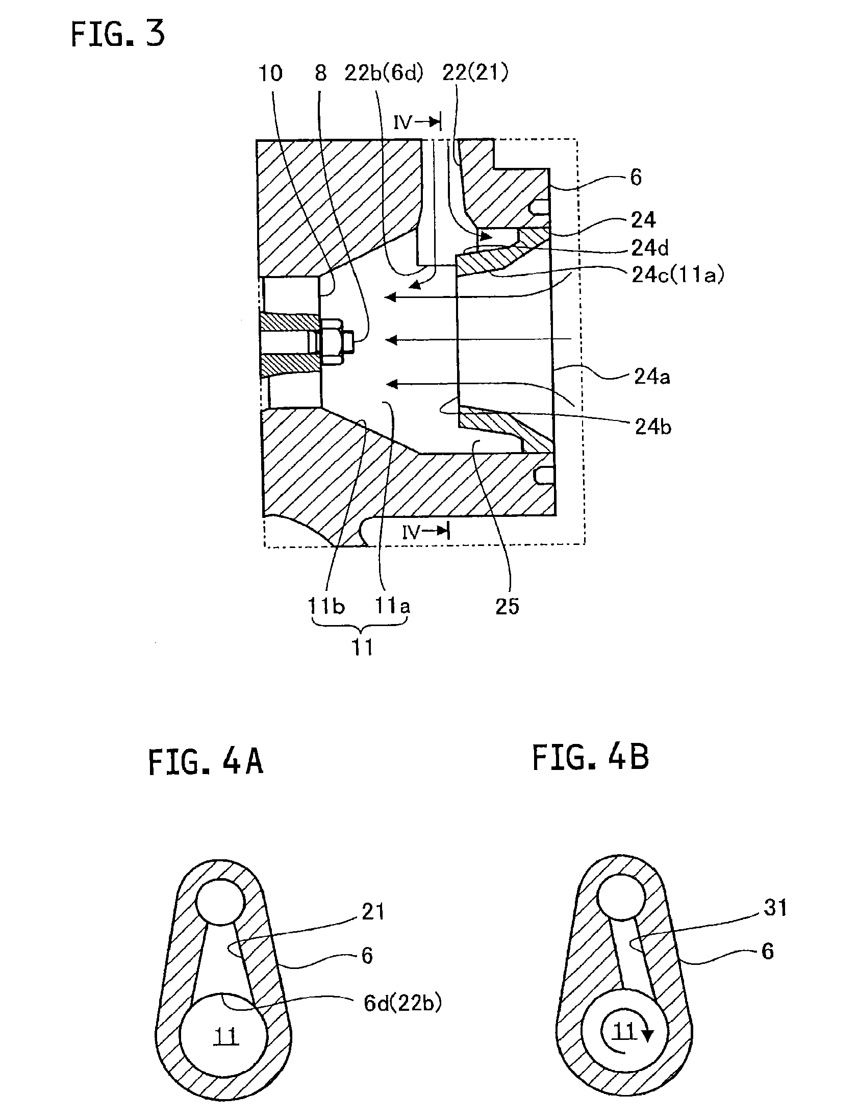
[0025]FIG. 1 is a sectional view schematically...


PUM


Abstract

A centrifugal compressor includes a housing that accommodates a wheel. The housing includes an air intake space formed on an entrance side of the wheel; a flow passage to guide fluid compressed by the wheel to the outside of the housing; a return flow passage opened on each wall surface of the air intake space and the flow passage to circulate a part of the fluid in the flow passage to the air intake space without passing through the wheel; and an introduction portion provided in the air intake space, and having an inner peripheral surface that forms a flow passage to guide the fluid from the outside of the housing to the wheel. A downstream end of the inner peripheral surface in a flowing direction of the fluid is located inside in the radial direction of a shaft than the wall surface of the housing.

Description

CROSS REFERENCE TO RELATED APPLICATIONS[0001]This application is a continuation application of International Application No. PCT / JP2014 / 074804, filed on Sep. 19, 2014, which claims priority to Japanese Patent Application No. 2013-201054, filed on Sep. 27, 2013, the entire contents of which are incorporated by reference herein.BACKGROUND[0002]1. Technical Field[0003]The present disclosure relates to a centrifugal compressor and a turbocharger, in which formed is a return flow passage for circulating part of compressed air to the upstream side.[0004]2. Description of the Related Art[0005]A conventional turbocharger includes a bearing housing, a shaft that is rotatably held by the bearing housing, a turbine wheel provided at one end of the shaft, and a compressor wheel provided at the other end of the shaft. Such a turbocharger is connected with an engine. The exhaust gas discharged from the engine rotates the turbine wheel. With the rotation of the turbine wheel, the compressor wheel ...

Claims


Application Information

Patent Timeline
Patent Type & Authority Applications(United States)
IPC IPC(8): F04D27/00F04D29/28F04D29/42F04D17/10
CPCF04D27/009F04D29/4233F04D29/284F04D17/10F04D25/024F04D27/0238F04D29/4213F04D29/441F04D29/663F04D29/681F04D29/684F04D29/685F05D2220/40F05D2250/51F05D2260/606F05D2260/96
Inventor MURAYAMA, TOMOKAZU
Owner IHI CORP
Why Eureka
Try Eureka