Eureka AIR delivers breakthrough ideas for toughest innovation challenges, trusted by R&D personnel around the world.

Testing device

Active Publication Date: 2016-05-12
PRIMAX ELECTRONICS LTD
View PDF21 Cites 1 Cited by
  • Summary
  • Abstract
  • Description
  • Claims
  • Application Information

AI Technical Summary

Benefits of technology

The present invention provides a testing device using an electrically conductive plate instead of a plastic plate to avoid electrostatic discharge and a structure to separate the testing probe from the electrically conductive plate to prevent electrical leakage and damage to the under-test object without affecting the measurement accuracy.

Problems solved by technology

If the procedure of testing the circuit board is not done and some defects are found after the electronic device is assembled, the manufacturer has to disassemble the electronic device to debug the circuit board.
It is time-consuming to disassemble the electronic device to debug the circuit board.
Due to the electrostatic discharge effect, the possibility of causing damage of the circuit board 10 increases.

Method used


Image

  • Testing device
  • Testing device
  • Testing device

Examples


Embodiment Construction

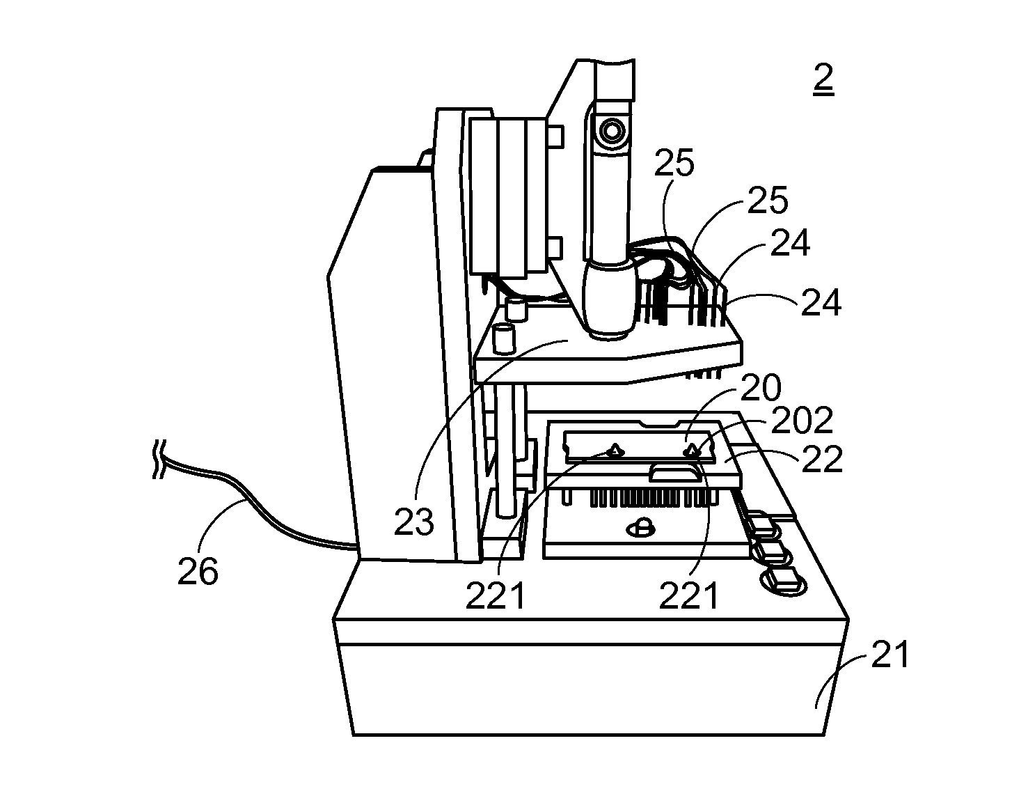
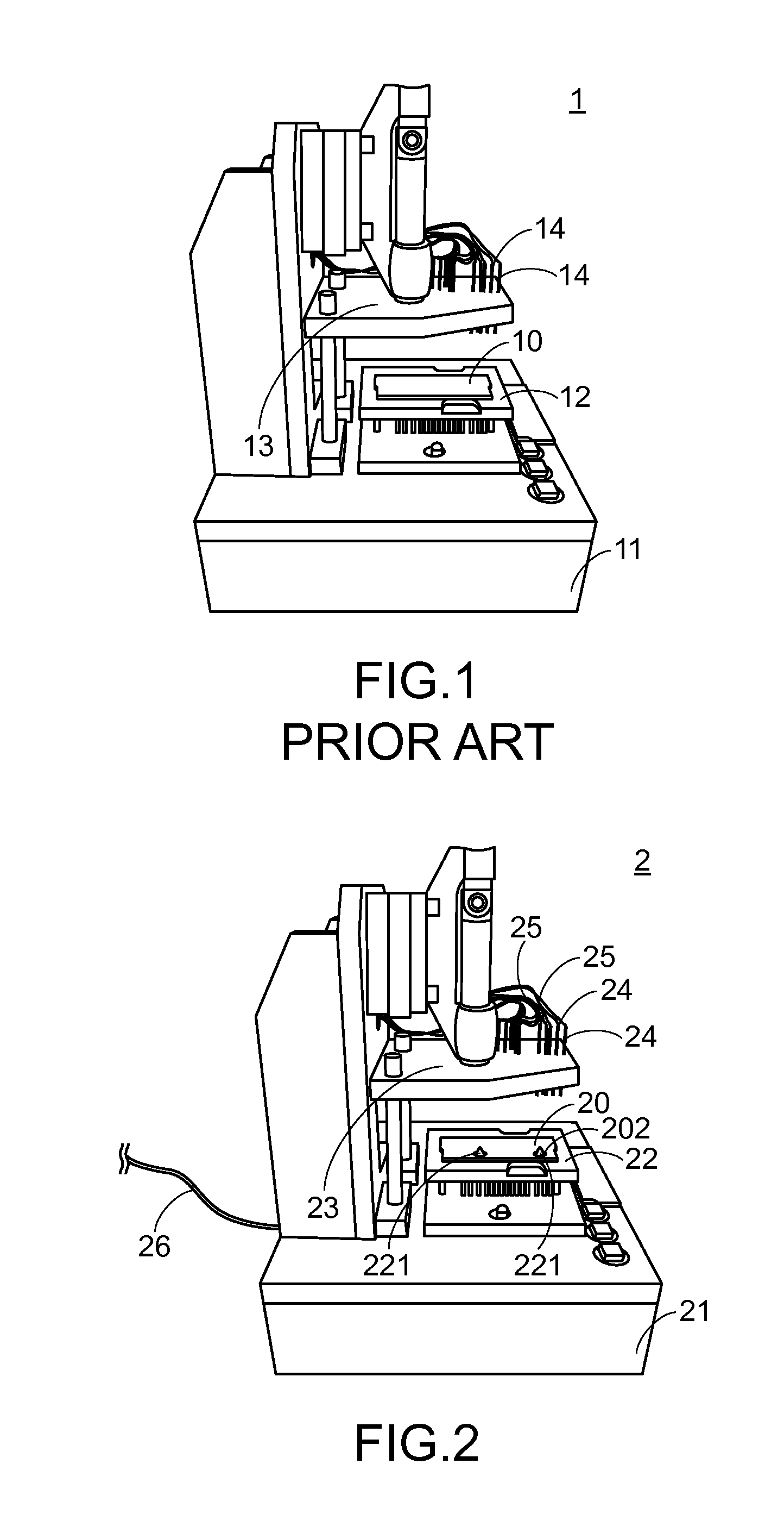
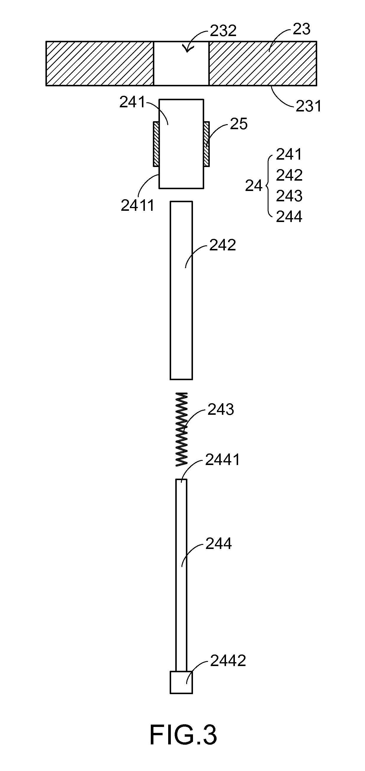
[0017]For eliminating the drawbacks of the conventional technologies, the present invention provides a testing device. Hereinafter, the structure of a detecting device of the present invention will be illustrated with reference to FIGS. 2 and 3. FIG. 2 is a schematic perspective view illustrating the structure of a detecting device according to a first embodiment of the present invention. FIG. 3 is a schematic partial exploded view illustrating the relationship between an electrically conductive plate and a testing probe of the testing device according to the first embodiment of the present invention. The testing device 2 comprises a base body 21, a holder 22, an electrically conductive plate 23, plural testing probes 24, plural insulation structures 25 (see FIG. 4) corresponding to the plural testing probes 24, and a transmission wire 26. The holder 22 is disposed on the base body 21 for supporting an under-test object 20. The electrically conductive plate 23 is disposed on the bas...


PUM


Abstract

A testing device includes a base body, a holder, an electrically conductive plate, plural testing probes and plural insulation structures. The testing device of the present invention uses the electrically conductive plate to replace the plastic plate of the conventional testing device. Consequently, the electrostatic discharge effect is avoided. Moreover, the insulation structure is arranged between the testing probe and the electrically conductive plate to separate the testing probe from the electrically conductive plate so as to avoid the electric leakage problem. Consequently, the testing device of the present invention is capable of avoiding the electrostatic discharge effect without causing damage of the under-test object and reducing the measurement accuracy.

Description

FIELD OF THE INVENTION[0001]The present invention relates to a testing device, and more particularly to a testing device for testing an under-test object.BACKGROUND OF THE INVENTION[0002]With increasing development of science and technology, electronic devices become more and more popular to personal users. The widely-used electronic devices include for example desktop computers, notebook computers, smart phones, tablet computers or the like. Each of these electronic devices has at least one circuit board. Moreover, at least one electronic component is fixed on the circuit board for executing a specified function. Moreover, through the cooperation of plural electronic components on the circuit board, the electronic device can be driven and operated. Generally, plural electrical contacts are formed on the circuit board so as to be electrically connected with these electronic components.[0003]Generally, in the fabrication of the electronic device, a testing method should be performed ...

Claims


Application Information

Patent Timeline
IPC IPC(8): G01R1/18G01R31/02
CPCG01R31/02G01R1/18G01R1/06722G01R31/2808
Inventor CHANG, PEI-MING
Owner PRIMAX ELECTRONICS LTD
Why Eureka
Eureka Blog
Learn More