
Capacitive Touch Circuit and Touch Sensor and Capacitive Touch System Using The Same

a capacitive touch and touch sensor technology, applied in the field of capacitive touch circuits, can solve the problems of lowering the accuracy of determining the touch location and inaccurate and achieve the effect of enhancing the sensing signal, lowering the accuracy of determining the touch location and accurate reading of the touch signal

Inactive Publication Date: 2016-05-12
APEX MATERIAL TECH CORP +1
View PDF0 Cites 8 Cited by
  • Summary
  • Abstract
  • Description
  • Claims
  • Application Information

AI Technical Summary

Benefits of technology

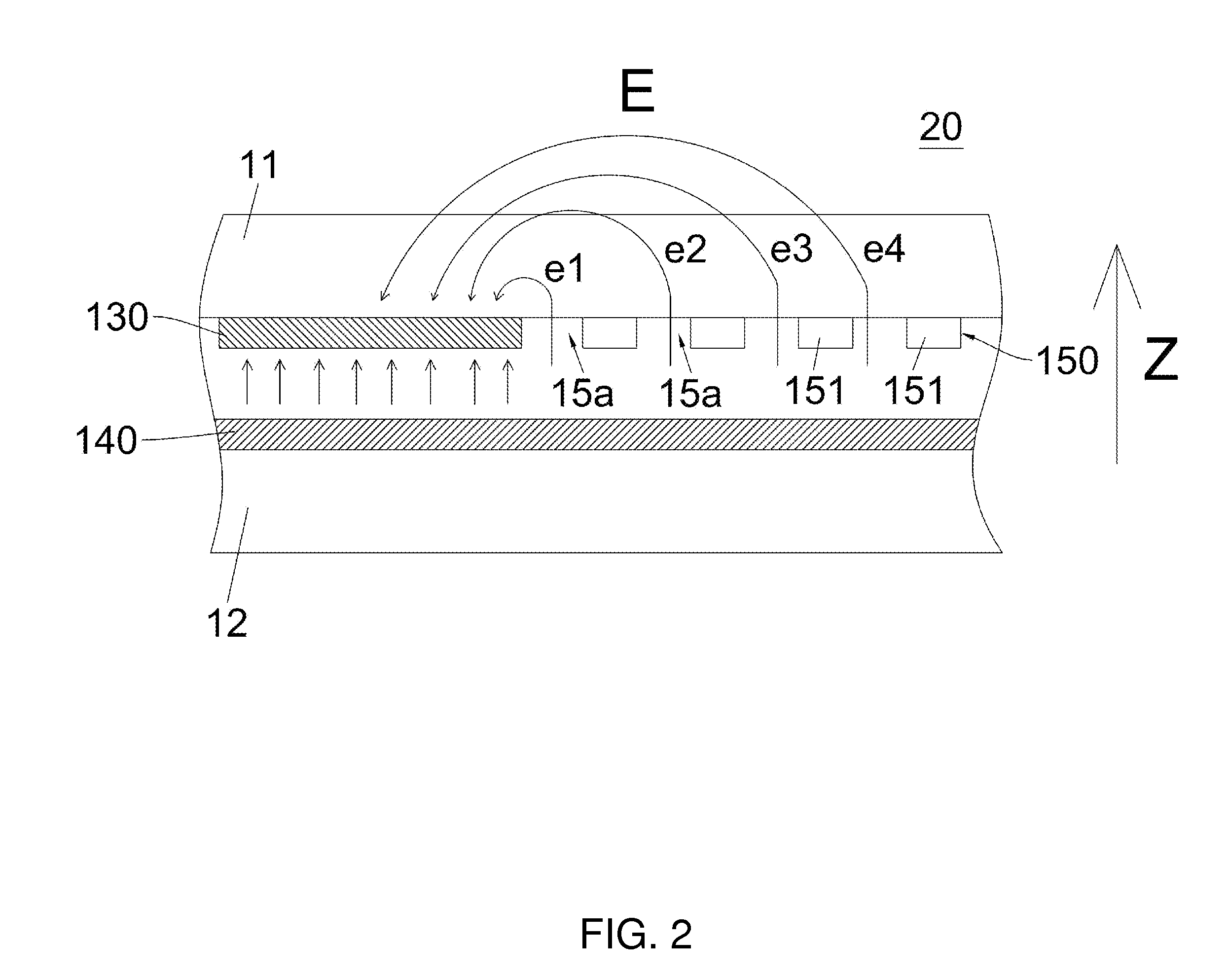
The invention provides a capacitive touch circuit, sensor, and system that solve the problems of inaccurate touch signal reading and lowered touch location accuracy. This is achieved by using insulation slits to pass through the electric field, which prevents interference between signals and improves the sensing signal. Overall, the invention enhances the accuracy of touch signal reading and improves the accuracy of touch location determination.

Problems solved by technology

This would lead to inaccurate reading of the touch signal and lowering the accuracy of determining the touch location.

Method used


Image

  • Capacitive Touch Circuit and Touch Sensor and Capacitive Touch System Using The Same
  • Capacitive Touch Circuit and Touch Sensor and Capacitive Touch System Using The Same
  • Capacitive Touch Circuit and Touch Sensor and Capacitive Touch System Using The Same

Examples


Embodiment Construction

[0033]Reference will now be made in detail to elaborate the contents, features and results of the present embodiments of the invention, examples of which are illustrated in the accompanying drawings. The directional terms in the detailed description, e.g. “upper”, “lower”, “upwardly”, “top” and “bottom”, and the number of elements, are used for the purpose of clarity, and are not intend to limit the scope of the invention.

[0034]In the embodiments of the present invention, a capacitive touch circuit, a capacitive touch sensor and a capacitive touch system are disclosed.

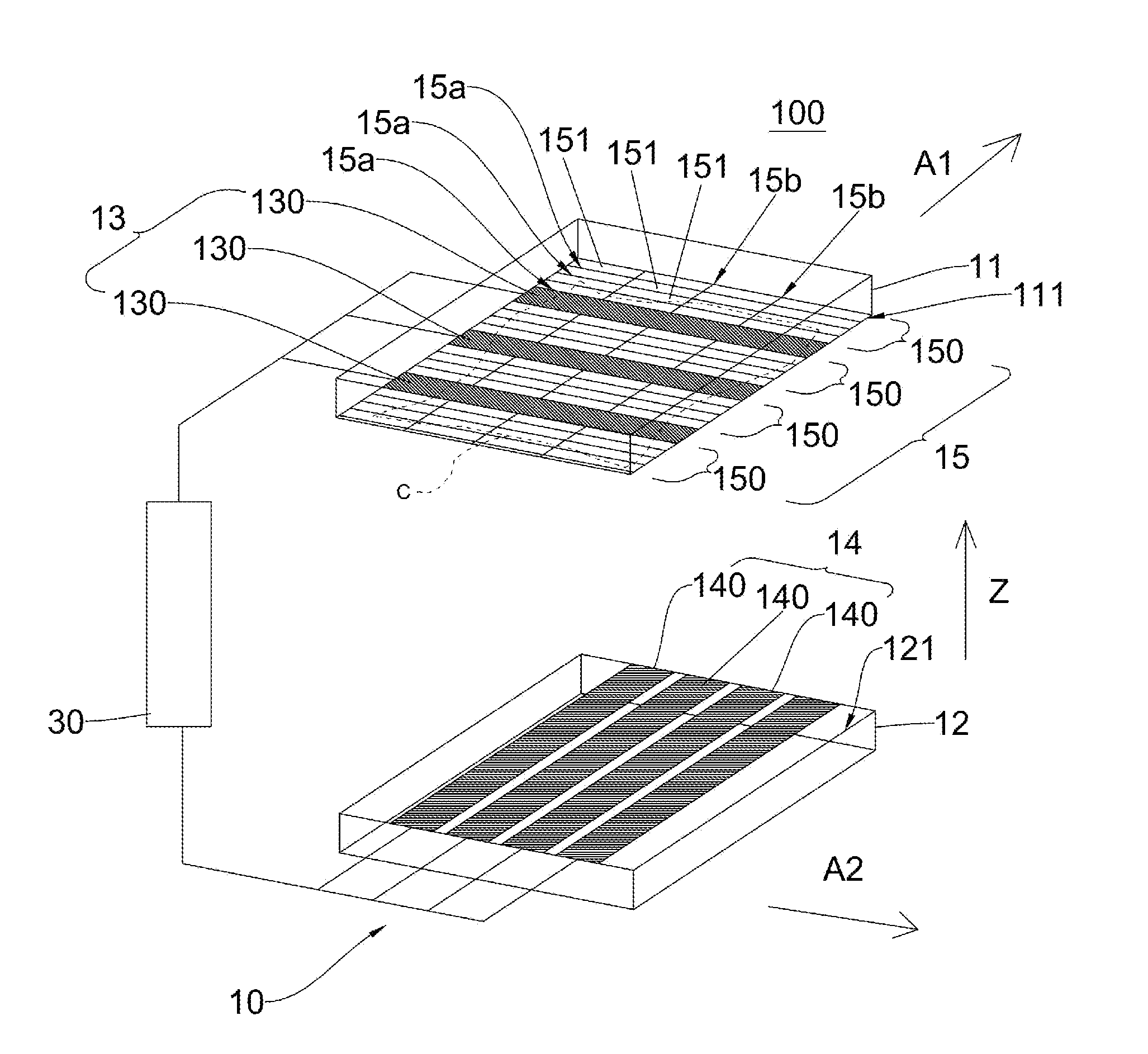
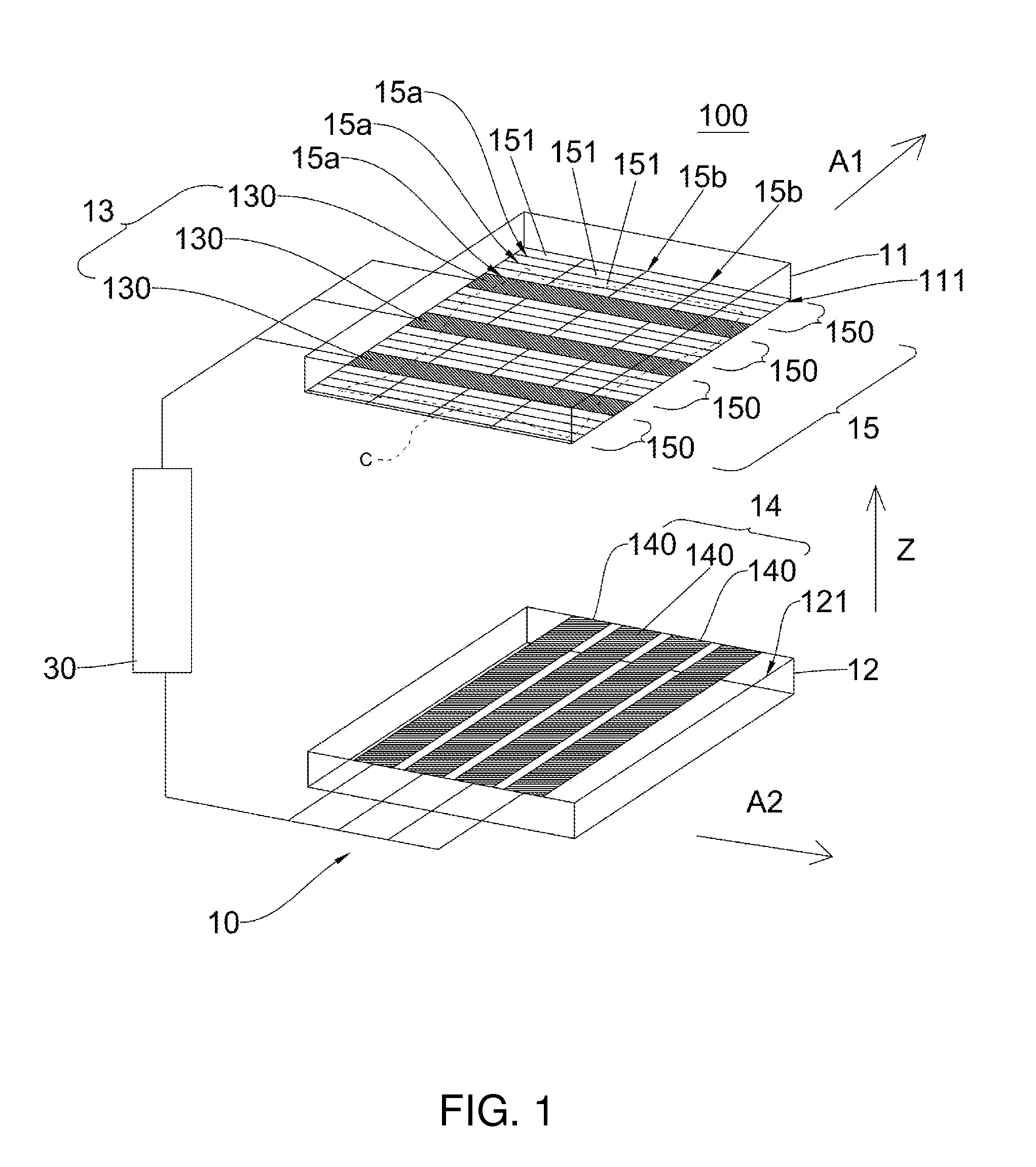
[0035]Please refer to FIG. 1, which is a perspective view of a capacitive touch system according to one embodiment of the invention. The capacitive touch system 100 includes a capacitive touch sensor 10 and a controller 30. The controller 30 is electrically connected to the capacitive touch sensor 10 for outputting signals to and receiving signals from the capacitive touch sensor 10.

[0036]The capacitive sensor 10 of th...


PUM


Abstract

A capacitive touch system including a capacitive touch sensor and a controller is provided. The sensor includes a first and a second substrate, a first and a second electrode arrangement, and a floating electrode arrangement. The first electrode arrangement and the floating electrode arrangement are disposed on different parts of the first substrate. The first and the second electrode arrangements are used to produce an electric field. A change in the characteristic of the electric field occurs when the touch sensor is touched. The floating electrode arrangement has multiple insulation slits for the electric field to pass through. The first and the floating electrode arrangements are electrically insulated through the slits, and multiple floating electrode units in the floating electrode arrangement are also electrically insulated from one another through the slits. The controller outputs a control signal based on the change in the characteristic of the electric field.

Description

RELATED APPLICATIONS[0001]This application claims priority to Taiwan patent application, No. 103116103, filed on May 6, 2014, entitled “CAPACITIVE TOUCH CIRCUIT AND TOUCH SENSOR AND CAPACITIVE TOUCH SYSTEM USING THE SAME”, which is hereby incorporated by reference in its entirely.BACKGROUND OF THE INVENTION[0002]1. Technical Field[0003]The present invention relates to a capacitive touch circuit. More particularly, the present invention relates to a capacitive touch sensing circuit using a projected electric field.[0004]2. Description of Related Art[0005]There are various types of touch panels in the market, including capacitive, resistive, optical, electromagnetic, and acoustic wave touch panel. Among these types of touch panels, the capacitive touch panel has the merits including high transparency, good responsiveness, accurate touch sensing, multi-touch compatibility, and compact package size, and therefore has been widely used in products of various sizes. In addition to that, th...

Claims


Application Information

Patent Timeline
Patent Type & Authority Applications(United States)
IPC IPC(8): G06F3/041G06F1/16G06F3/044
CPCG06F3/0418G06F2203/04101G06F1/16G06F3/044G06F3/0445
Inventor KAO, PING-JUNGLIN, I-TE
Owner APEX MATERIAL TECH CORP
Learn More