Particle beam therapy system

a beam therapy and particle technology, applied in the field of particle beam therapy system, can solve the problem of not being able to perform simultaneous treatment in the plurality of treatment rooms

Active Publication Date: 2016-05-19
MITSUBISHI ELECTRIC CORP
View PDF9 Cites 4 Cited by
  • Summary
  • Abstract
  • Description
  • Claims
  • Application Information

AI Technical Summary

Benefits of technology

[0008]According to the particle beam therapy system of the invention, the beam-path changer of the beam transport system and the emitter of the accelerator are controlled based on the plurality of respiratory gate signals and the time-sharing signal so that, with respect to the plurality of particle beam irradiation apparatuses in which treatment is per

Problems solved by technology

Thus, it is basically unable to perform treatment

Method used


Image

  • Particle beam therapy system
  • Particle beam therapy system
  • Particle beam therapy system

Examples


embodiment 1

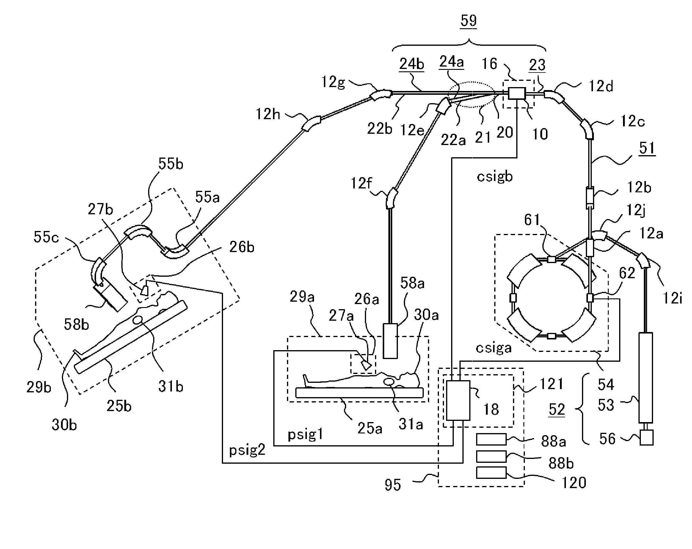
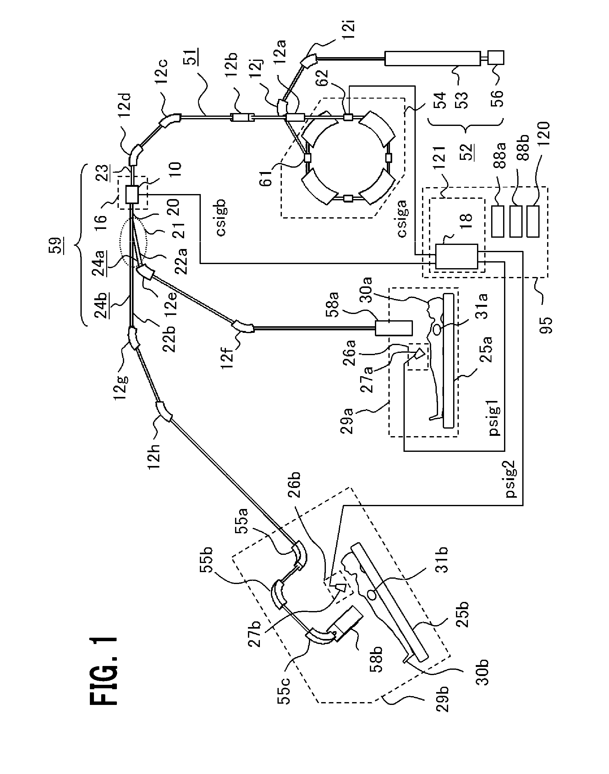
[0057]FIG. 1 is a configuration diagram showing a particle beam therapy system according to Embodiment 1 of the invention. FIG. 2 is a schematic configuration diagram of a particle beam irradiation apparatus in FIG. 1. A particle beam therapy system 51 includes a beam generation apparatus 52, a beam transport system 59 and a plurality of particle beam irradiation apparatuses 58a, 58b. The particle beam irradiation apparatus 58b is placed in a rotary gantry (not shown) provided in a treatment room 29b. The particle beam irradiation apparatus 58a is placed in a treatment room 29a including no rotary gantry. Note that, in FIG. 1, for simplification's sake, description will be made assuming that the number of treatment rooms is two; however, this does not mean that the number of treatment rooms is limited to two in the invention.

[0058]The beam generation apparatus 52 includes an ion source 56, a linear accelerator 53 and a circular accelerator (hereinafter, referred to simply as “accele...

embodiment 2

[0086]FIG. 10 is a configuration diagram showing a particle beam therapy system according to Embodiment 2 of the invention, and FIG. 11 is a diagram showing a beam-path controller in FIG. 10. FIG. 12 is a diagram showing a damper placed near a duct branching point in FIG. 10, and FIG. 13 is a timing chart illustrating a beam distribution to a plurality of treatment rooms according to Embodiment 2 of the invention. The particle beam therapy system 51 of Embodiment 2 differs from the particle beam therapy system 51 of Embodiment 1 in that a damper 11 for shutting off the charged particle beam 81 is provided in a duct branching section 21 placed at the downstream side of the beam-path changer 16, and in that the treatment management device 95 includes a beam-path controller 19 for outputting to the beam-path changer 16, a kicker control signal csigd that is a beam-path changer control signal. The beam-path controller 19 includes, in place of the emitter control-signal generator 36 and ...

embodiment 3

[0094]FIG. 15 is a configuration diagram showing a particle beam therapy system according to Embodiment 3 of the invention, and FIG. 16 is a diagram showing a beam-path controller in FIG. 15. FIG. 17 is a timing chart illustrating a beam distribution to a plurality of treatment rooms according to Embodiment 3 of the invention. When irradiation requests from the plurality of treatment rooms 29 are overlapping, for example, when the respiratory gate signal gsig1 for the treatment room 1 is in “ON” state and the respiratory gate signal gsig2 for the treatment room 2 is in “ON” state, the particle beam therapy system 51 of Embodiment 3 controls so as to make switching of the charged particle beam 81 between toward the respective corresponding treatment rooms 1, 2 (treatment rooms 29a, 29b) in a short time, as shown below.

[0095]The treatment management device 95 in Embodiment 3 differs from that in Embodiment 1 in including a beam-path controller 63 that outputs a kicker control signal c...


PUM


Abstract

In the particle beam therapy system, a beam transport system includes a beam-path changer for changing a beam path so as to transport a charged particle beam to any one of the plurality of particle beam irradiation apparatuses; and a treatment management device includes a beam-path controller that generates an emitter control signal for controlling an emitter of an accelerator and a beam-path changer control signal for controlling the beam-path changer so that, with respect to the plurality of particle beam irradiation apparatuses in which treatment is performed at the same treatment period of time, the charged particle beam is transported to each one of the plurality of particle beam irradiation apparatuses for each time period allocated thereto.

Description

TECHNICAL FIELD[0001]The present invention relates to a particle beam therapy system used for medical use or research use, and in particular, relates to a particle beam therapy system which can transport a beam to a plurality of treatment rooms as if simultaneously by time-sharing.BACKGROUND ART[0002]Heretofore, among particle beam therapy systems, there have been reported those with the presence of a plurality of treatment rooms. In such conventional particle beam therapy systems, beam paths are each configured to guide a beam to selected one of the treatment rooms by way of electromagnets of a beam transport system referred to as an HEBT (High Energy Beam Transport) system. Thus, it is basically unable to perform treatment simultaneously in the plurality of treatment rooms. Meanwhile, it is general to perform switching of the beam path by use of a bending magnet.[0003]In Patent Document 1, there is described a particle beam therapy system that, for the purpose of improving through...

Claims


Application Information

Patent Timeline
IPC IPC(8): A61N5/10
CPCA61N5/1079A61N2005/1074A61N5/1068A61N5/1067A61N2005/1087
Inventor IWATA, TAKAAKIHARADA, HISASHIIKEDA, MASAHIROPU, YUEHU
Owner MITSUBISHI ELECTRIC CORP
Why Eureka
Try Eureka