Control apparatus and control system controlling protective apparatus for protecting passenger of vehicle or pedestrian

a control apparatus and control system technology, applied in the direction of pedestrian/passenger safety arrangement, vehicular safety arrangement, instruments, etc., can solve the problem of failure, failure to consider whether a faulty sensor had been diagnosed as faulty before is connected to the control apparatus, and failure to detect a faulty external sensor

Active Publication Date: 2016-05-19
BOSCH CORP
View PDF1 Cites 107 Cited by
  • Summary
  • Abstract
  • Description
  • Claims
  • Application Information

AI Technical Summary

Benefits of technology

[0007]In addition, in the assembly line for vehicles, to ensure the traceability (history) of a vehicle and an external sensor attached to the vehicle, a barcode label or two-dimensional barcode label on which information including the model and individual identifying ID of the external sensor is printed may be attached to the external sensor. That is, before an external sensor is assembled to a vehicle in the assembly line for vehicles, the traceability of external sensor to be attached to the vehicle is ensured using a computer system by reading the barcode of the external sensor with a barcode reader or the like. However, to increase the room space of a vehicle or for other reasons, the size reduction of an external sensor has been requested recently. Size reduction of an external sensor makes it difficult to obtain sufficient space to attach a barcode label to an external sensor. Since it is difficult for a person to visually identify an external sensor without a barcode label, the method for surely preventing faulty sensors from being put on the market has been requested.
[0028]According to the invention of the present application, it is possible to determine whether a faulty sensor having been diagnosed as being faulty before is connected to the control apparatus.

Problems solved by technology

However, the prior art does not consider a determination as to whether a faulty sensor having been diagnosed as being faulty before is connected to the control apparatus.
A failure that occurs again is, for example, a failure that occurs due to a short-circuit of the circuit on a board of the external sensor because a metal piece moves on the board due to vibration of the vehicle when, for example, a small conductive metal piece or the like is included during assembly process of the housing of the external sensor.
In addition, when a faulty external sensor having a failure difficult to reproduce is found in the assembly line for vehicles, if the faulty external sensor is erroneously assembled to a vehicle, the faulty external sensor cannot be detected until a failure occurs again.
Size reduction of an external sensor makes it difficult to obtain sufficient space to attach a barcode label to an external sensor.

Method used


Image

  • Control apparatus and control system controlling protective apparatus for protecting passenger of vehicle or pedestrian
  • Control apparatus and control system controlling protective apparatus for protecting passenger of vehicle or pedestrian
  • Control apparatus and control system controlling protective apparatus for protecting passenger of vehicle or pedestrian

Examples


first embodiment

[0111] since the individual identifying ID of an external sensor diagnosed as being faulty is recorded in the faulty sensor ID recording unit 184, by comparing this individual identifying ID with the individual identifying ID of the external sensor currently connected to the air bag ECU 100, a determination can be made as to whether a faulty sensor having been diagnosed as being faulty before is connected to the air bag ECU 100.

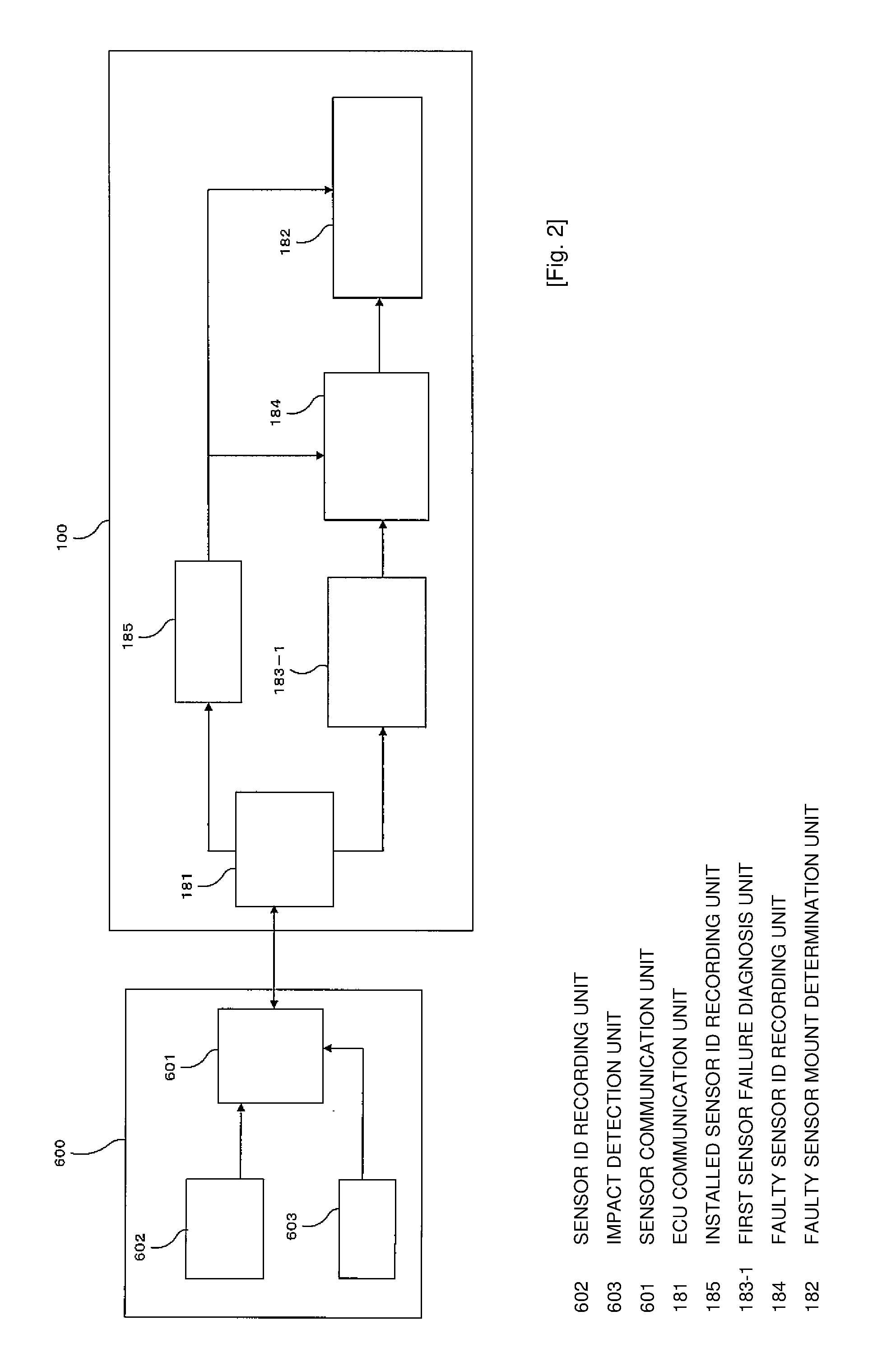
[0112]Next, the functional blocks of an external sensor and an air bag ECU according to a second embodiment will be described. FIG. 4 is a diagram illustrating the functional blocks of an air bag control system (air bag ECU and external sensor) according to the second embodiment. The detailed description of components that are the same as in the first embodiment is omitted.

[0113]The front right acceleration sensor 600 includes the sensor communication unit 601, the sensor ID recording unit 602, the impact detection unit 603, and an in-sensor failure diagnosis...

second embodiment

[0126] by recording the individual identifying ID of the external sensor diagnosed as being faulty by the external sensor in the faulty sensor ID recording unit 184 and comparing this individual identifying ID with the individual identifying ID of the external sensor currently connected to the air bag ECU 100, a determination can be made as to whether a faulty sensor having been diagnosed as being faulty before is connected to the air bag ECU 100.

[0127]Next, the functional blocks of an external sensor and an air bag ECU according to a third embodiment will be described. FIG. 6 is a diagram illustrating the functional blocks of an air bag control system (air bag ECU and external sensor) according to the third embodiment. The detailed description of components that are the same as in the first or second embodiment is omitted.

[0128]The front right acceleration sensor 600 includes the sensor communication unit 601, the impact detection unit 603, and a failure history recording unit 605....

fourth embodiment

[0165] an external sensor diagnoses whether the external sensor is faulty and, if it is faulty, the failure information is written to the external sensor according to a write request from the air bag ECU 100, so the external sensor holds its failure history data in the failure history recording unit 605. Since the external sensor sends failure history data to the air bag ECU 100 in initialization processing, the air bag ECU 100 can determine whether a faulty sensor having been diagnosed as being faulty before is connected to the air bag ECU 100 based on the failure history data.

[0166]Next, the functional blocks of an external sensor and an air bag ECU according to a fifth embodiment will be described. FIG. 10 is a diagram illustrating the functional blocks of an air bag control system (air bag ECU and external sensor) according to the fifth embodiment. The detailed description of components that are the same as in the first to fourth embodiments is omitted.

[0167]The front right acce...


PUM


Abstract

An air bag ECU includes an ECU communication unit communicating with an external sensor (for example, a front right acceleration sensor) and a faulty sensor mount determination unit determining whether a faulty sensor having been diagnosed as being faulty before is connected to the air bag ECU based on failure history data indicating whether the external sensor has been diagnosed as being faulty before. The faulty sensor mount determination unit compares identification data recorded in, for example, a faulty sensor ID recording unit, for individually identifying an external sensor having been diagnosed as being faulty before with the identification data of the external sensor connected to the air bag ECU and determines whether a faulty sensor is connected to the air bag ECU.

Description

BACKGROUND OF THE INVENTION[0001]The present invention relates to a control apparatus and control system that controls a protective apparatus for protecting passengers in a vehicle or pedestrians.[0002]Conventionally, a vehicle has been provided with a protective apparatus (such as, for example, an air bag) for protecting passengers in a vehicle or pedestrians and the activation of the protective apparatus is controlled by a control apparatus. An external sensor (such as, for example, an acceleration sensor for detecting an impact on the vehicle) for determining whether the protective apparatus is activated is connected to the control apparatus. When the external sensor detects an impact on the vehicle, the control apparatus dampers an impact on passengers in the vehicle by expanding the air bag or dampers an impact on pedestrians by lifting the hood of the vehicle.[0003]Since the external sensor becomes faulty due to various causes, the prior art may perform failure diagnosis of th...

Claims


Application Information

Patent Timeline
Patent Type & Authority Applications(United States)
IPC IPC(8): G07C5/08G07C5/00
CPCG07C5/0841G07C5/008G07C5/0808B60R2021/01184B60R2021/01068B60R21/01
Inventor AKANUMA, RYOJIROARAI, KENJIMATSUURA, KEISUKE
Owner BOSCH CORP
Why Eureka
Try Eureka