Method of manufacturing polarizing plastic lens

a technology of polarizing plastic and manufacturing method, which is applied in the field of manufacturing polarizing plastic lenses, can solve the problems of increasing the tendency to curl, affecting the quality of polarizing film, so as to improve the rigidity of polarizing film, facilitate handling, and prevent curling

Active Publication Date: 2016-05-26
EHS LENS PHILIPPINES
View PDF9 Cites 11 Cited by
  • Summary
  • Abstract
  • Description
  • Claims
  • Application Information

AI Technical Summary

Benefits of technology

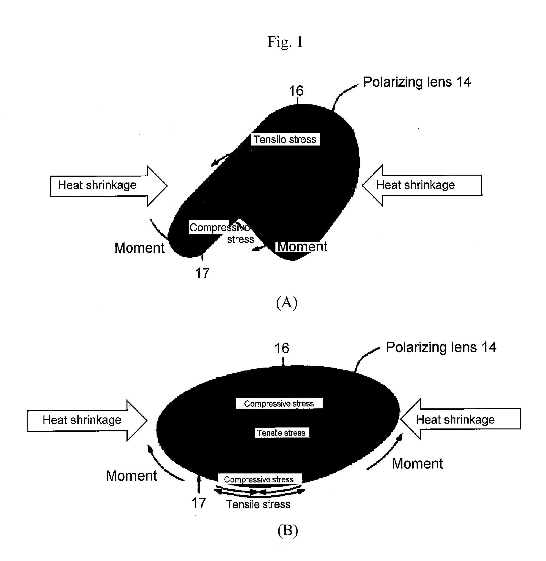
[0032]As described above based on FIG. 1, the rigidity of the polarizing film is increased by subjecting it to a reversing step following curved surface processing, thereby preventing curling and facilitating handling. Due to its high rigidity, the film tends not to crack and has enhanced shape retention. Accordingly, deformation of the film due to the casting pressure in the course of casting lens monomer into the cavity of the casting mold in which the polarizing film has been positioned and unintended contact with the molding surface of the mold can be inhibited. Inhibiting deformation of the polarizing film during polymerization and curing can improve the yield and contribute to providing a polarizing lens that affords high optical performance with little distortion. The tendency of the polarizing film not to come into contact with the molding surfaces of the mold can allow the polarizing film to be positioned near the molding surface of the mold for polymerization and curing. As set forth further below, this point is advantageous for fabricating thin polarizing lenses. The fact that the polarizing film is of high rigidity can facilitate the operation of holding the film when assembling the casting mold including the polarizing film and in the step of measuring the shape of the film, set forth further below. As set forth above, the polarizing film the concave and convex surfaces of which are reversed following curved surface processing can contribute to enhancing the productivity and quality of the polarizing lens in which the film has been embedded.

Problems solved by technology

In particular, since a polarizing film that has been curved (processed to impart a curved surface) by press molding so as to conform to the direction of the lens curve is used in the casting method, the tendency to curl is exacerbated and handling of the polarizing film becomes difficult.
When the polarizing film ends up curling in processing following cutting, handling of the polarizing film becomes difficult, productivity tends to drop, and the performance of the polarizing plastic lens that is manufactured and the quality of its external appearance tend to diminish.

Method used


Image

  • Method of manufacturing polarizing plastic lens
  • Method of manufacturing polarizing plastic lens
  • Method of manufacturing polarizing plastic lens

Examples


modification example 1

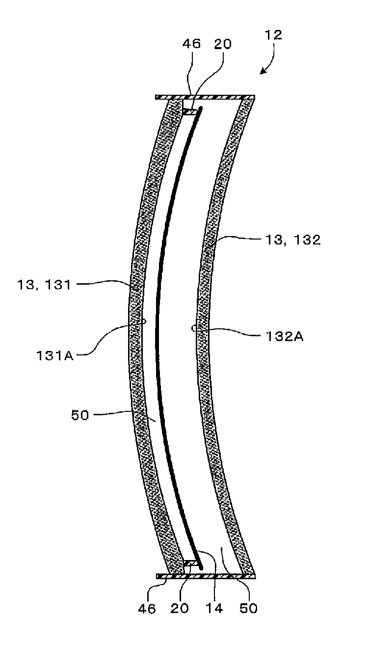
[0171]FIG. 22 is a sectional view schematically showing film positioning member 52 equipped with a guard jig 84 relating to the present modification example. In the above implementation mode, in the step of reversing polarizing film 14, the method of jetting air to promote the reversal of polarizing film 14 was disclosed. This jetting of air will sometimes cause problems by displacing unwanted curved portions 60 and impeding the turning inside out of polarizing film 14. Instead of vacuum suction of curved portions 60, or in combination with vacuum suction, as shown in FIG. 22, a guide jig 84 can be used to prevent curved portions 60 that have been cut off from displacing.

modification example 2

[0172]FIG. 23 is a plan view schematically showing polarizing film 14 equipped with ribs 85 relating to the present modification example. In the above implementation mode, curved portions 60 were provided along the edge of polymerizing film 14. Ribs 85 (positioned in a direction that intersects the radial direction of polarizing film 14 in a structure that protrudes to the convex surface 16 side) can be further molded into curved portion 60. The polarizing film tends to be deformed in a direction perpendicular to polarization axis 70 by the heat treatment. Providing ribs 85 can further inhibit the deformation of polarizing film 14 due to the heat treatment, and reduce astigmatismus defects.

modification example 3

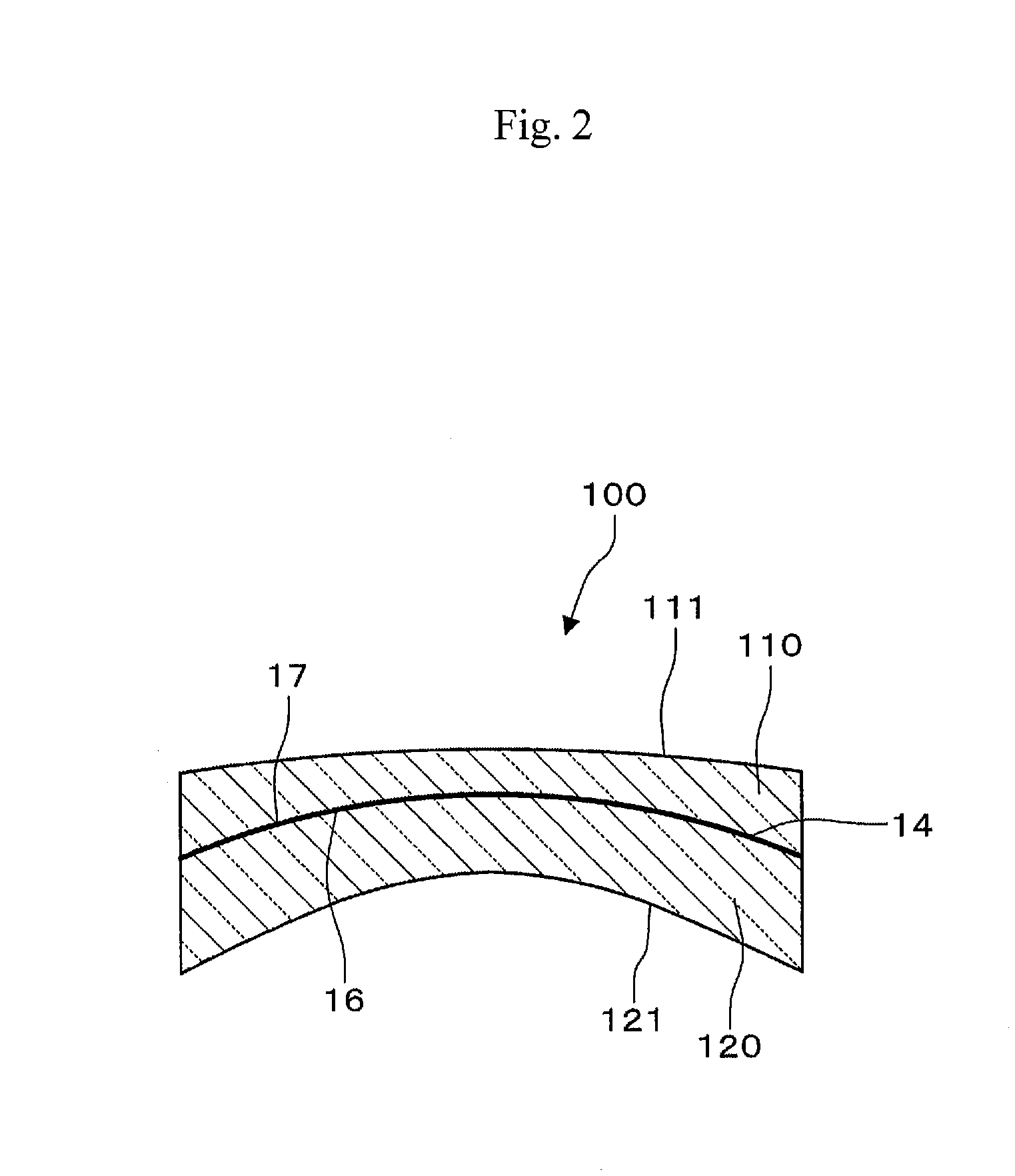
[0173]In the above implementation mode, a lens mold 12 was used to manufacture polarizing plastic lens 100. However, the method of employing a gasket having a member that supports polarizing film 14 and other known methods of manufacturing a polarizing plastic lens 100 using a polarizing film 14 that has been curved surface processed can also be applied. Since the reversed polarizing film 14 tends not to curl, it can also be used in these methods to stabilize the quality of the external appearance of polarizing plastic lens 100 and enhance manufacturing efficiency.

[0174]A further aspect of the present invention relates to a device of manufacturing a polarizing film.

[0175]The above manufacturing device includes a film reversing member set that is used in the reversing step to reverse the convex surface shape to a concave surface shape by pressing the polarizing film that has been curved surface processed;

[0176]the film reversing member set includes a pressing member with a convex sur...


PUM

PropertyMeasurementUnit
outer diameteraaaaaaaaaa
inner diameteraaaaaaaaaa
temperatureaaaaaaaaaa

Abstract

An aspect of the present invention relates to a method of manufacturing a polarizing plastic lens, which comprises a reversing step of reversing a convex surface shape into a concave surface shape by pressing a polarizing film that has been curved surface processed, a casting mold assembling step of assembling a casting mold having a cavity within which the reversed polarizing film is positioned with the reversed polarizing film, an upper mold, a lower mold, and a sealing member that maintains a spacing between the upper mold and the lower mold, and a polymerizing and curing step of casting a curable composition into the cavity, and polymerizing and curing the curable composition that has been cast to provide a polarizing plastic lens within which a polarizing film is positioned.

Description

CROSS-REFERENCE TO RELATED APPLICATIONS[0001]This application claims the benefit of priority to Japanese Patent Application No. 2012-250033 filed on Nov. 14, 2012, which is expressly incorporated herein by reference in its entirety.TECHNICAL FIELD[0002]The present invention relates to a method of manufacturing a polarizing plastic lens.BACKGROUND ART[0003]Polarizing lenses are often employed as lenses for nonprescription sunglasses (including fashion glasses) to protect the eyes because they function to block light. They are also employed as prescription eyeglass lenses.[0004]The polarizing lenses described in Japanese Unexamined Patent Publication (KOKAI) Nos. 2009-103773 and 2012-198389 (which are expressly incorporated herein by reference in their entirety) are polarizing lenses with polarizing films embedded within them. They are manufactured by casting a curable composition around a polarizing film, heating, and curing (called the casting method or casting polymerization method...

Claims


Application Information

Patent Timeline
Patent Type & Authority Applications(United States)
IPC IPC(8): B29D11/00G02B1/04G02C7/12
CPCB29D11/00644B29D11/00442G02C7/12G02C2202/16B29K2105/256B29K2029/04B29K2995/0034G02B1/041B29C39/10B29C39/24B29L2011/0016G02B5/30B29D11/00432B29D11/00528G02B5/3033
Inventor IHARA, MASAKISHIMIZU, HIROSHIITO, YOSHINOBUSHIMIZU, TOSHIHIKOTONOUCHI, KENICHI
Owner EHS LENS PHILIPPINES
Why Eureka
Try Eureka