Pneumatic tire

a technology of pneumatic tires and tires, applied in the field of pneumatic tires, can solve the problems of deteriorating steering stability on dry road surfaces

Active Publication Date: 2016-05-26
SUMITOMO RUBBER IND LTD
View PDF3 Cites 14 Cited by
  • Summary
  • Abstract
  • Description
  • Claims
  • Application Information

AI Technical Summary

Benefits of technology

[0025]In the pneumatic tire of the present invention, by being provided in the tread portion with a pair of the shoulder main grooves extending continuously in the tire circumferential direction on the most tread edge side, and the center main groove extending continuously in the tire circumferential direction on the inner side in the tire axial direction of the shoulder main groove,
[0026]The middle land portion is provided with the middle lateral groove extending from the shoulder main groove toward the inner side in the tire axial direction, while gradually decreasing the angle with respect to the tire circumferential direction.
[0027]The middle lateral groove is provided with the groove bottom sipe which extends along the middle lateral groove and opens in the groove bottom of the middle lateral groove. Such groove bottom sipe effectively absorbs water in the snow compressed in the middle lateral groove when running on snowy roads.

Problems solved by technology

The lateral grooves and sipes as described above, however, reduce the rigidity of the tread portion, and there is a problem of such that the steering stability on dry road surface is deteriorated.

Method used


Image

  • Pneumatic tire
  • Pneumatic tire
  • Pneumatic tire

Examples


working example

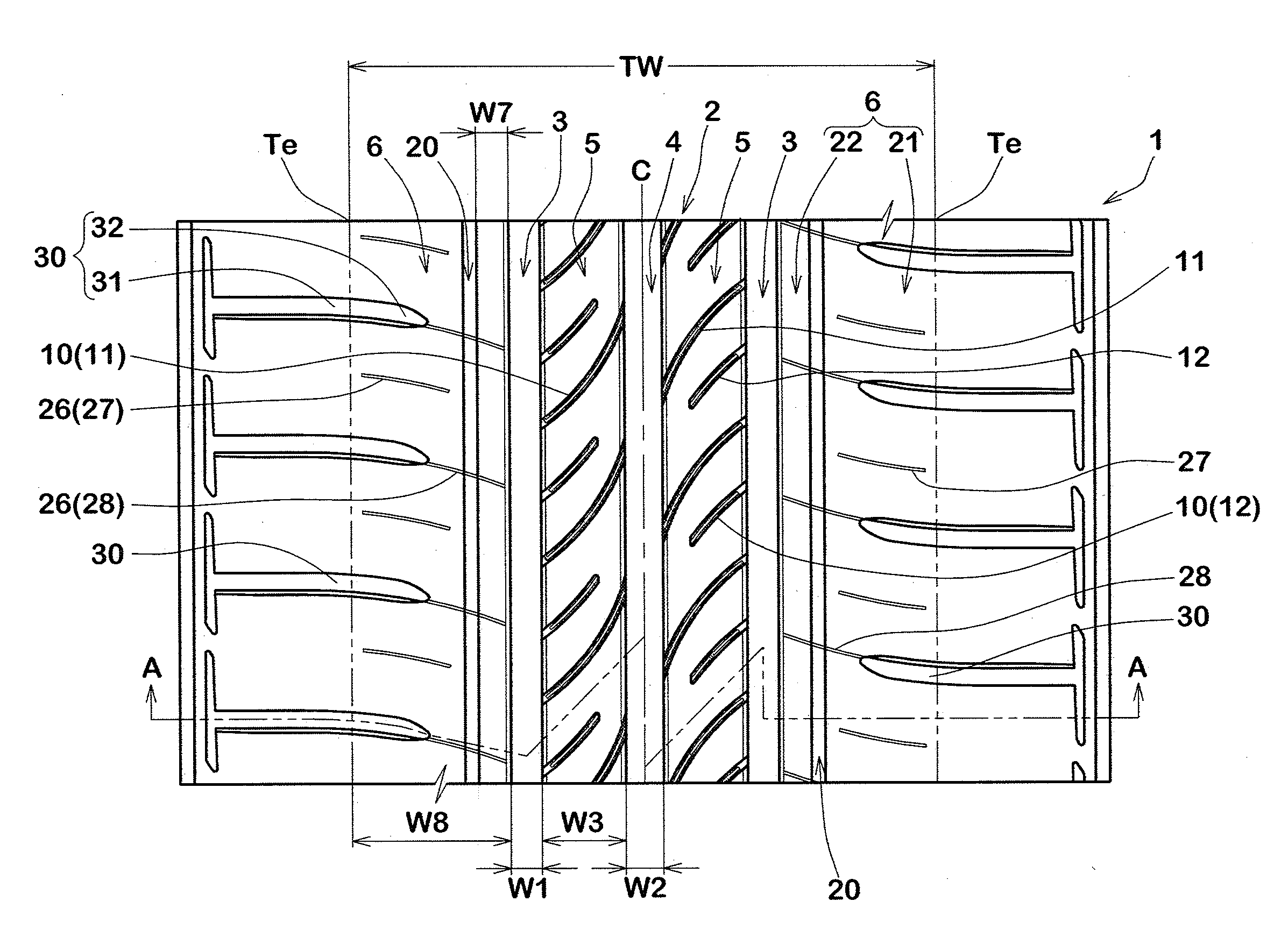
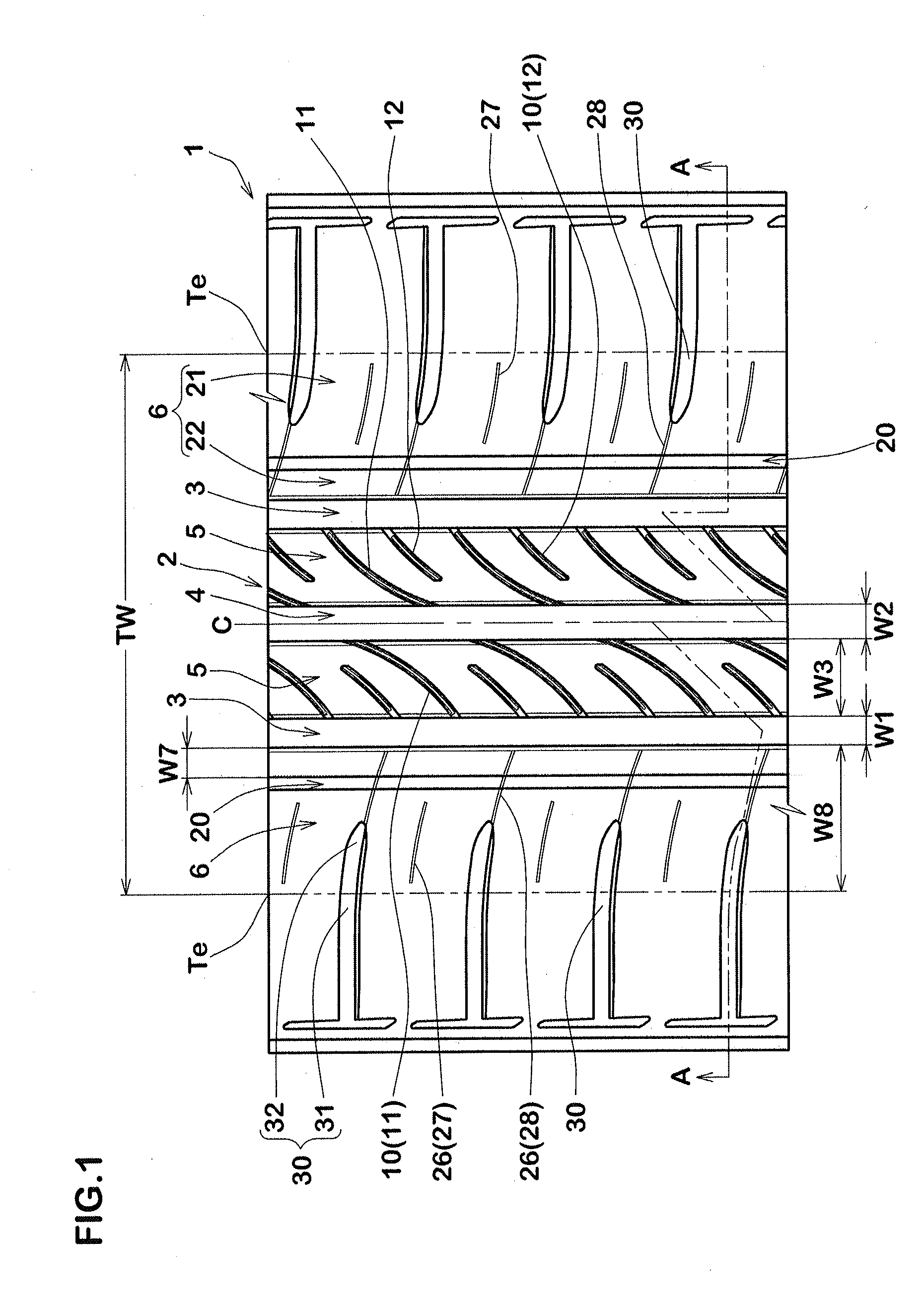
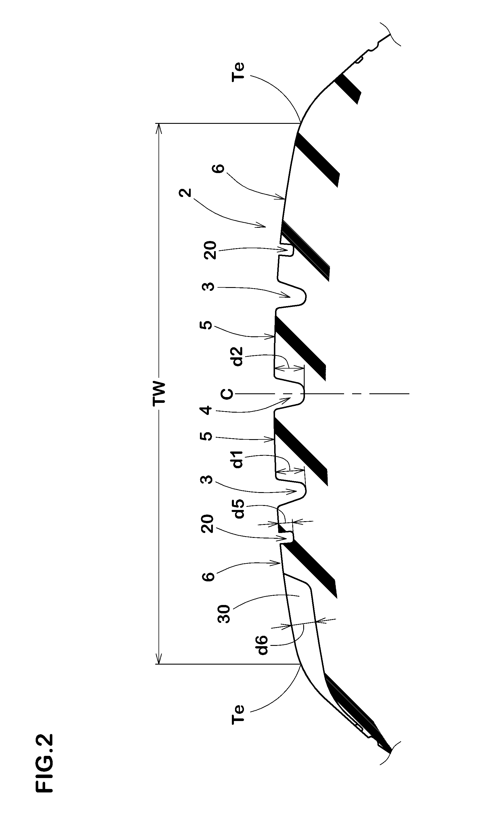
[0085]Pneumatic tires of size 185 / 60R15 having the basic pattern shown in FIG. 1 were experimentally manufactured based on the specifications shown in Table 1.

As a comparative example, a pneumatic tire not having a groove bottom sipe was experimentally manufactured.

Each test tire was tested for the steering stability on dry road surface and on-snow performance.

[0086]Common specifications to all of the tires and test methods are as follows.

[0087]mounting rim: 15×63

[0088]tire inner pressure: 230 kPa

[0089]test vehicle: front-wheel-drive vehicle,[0090]engine displacement 1300 cc

[0091]tire mounting position: all wheels

[0092]The steering stability when the test vehicle was traveling on a test course constituted by a dry asphalt road was evaluated by driver's sense.

The result is a grade based on comparative example 1 being 100, wherein the larger the number, the better the steering stability.

[0093]The on-snow performance when the test vehicle was traveling on snow was evaluated by driver's...


PUM


Abstract

To provide a pneumatic tire which is improved in on-snow performance, while maintaining steering stability on dry road surface. The pneumatic tire is provided in a tread portion 2 with a pair of shoulder main grooves 3, a center main groove 4, shoulder land portions 6, and middle land portions 5. The middle land portions 5 are provided with middle lateral grooves 10 extending from the shoulder main grooves 3 toward the inside in the tire axial direction, while gradually decreasing the angle with respect to tire circumferential direction. The middle lateral groove 10 is provided with a groove bottom sipe 15 opened in the groove bottom.

Description

TECHNICAL FIELD[0001]The present invention relates to a pneumatic tire which is improved in on-snow performance, while maintaining steering stability on dry road surface,BACKGROUND ART[0002]There has been proposed a pneumatic tire provided in the tread portion with sipes and lateral grooves extending in the tire axial direction.Such pneumatic tire is improved in running performance on snow (hereinafter, referred to as “on-snow performance”) by edge components of the lateral grooves and the sipes.[0003]The lateral grooves and sipes as described above, however, reduce the rigidity of the tread portion, and there is a problem of such that the steering stability on dry road surface is deteriorated.[0004]In the following Patent Document 1, there has been proposed a pneumatic tire in which the inclination direction of belt cords of a belt ply, and the inclination direction of lateral grooves in the tread portion are defined in order to suppress a decrease in the rigidity of the tread port...

Claims


Application Information

Patent Timeline
Patent Type & Authority Applications(United States)
IPC IPC(8): B60C11/12B60C11/03
CPCB60C11/125B60C11/0332B60C11/1272B60C11/1236B60C2011/0334B60C2011/0355B60C2011/0367B60C2011/0365B60C2011/0353B60C11/0306B60C2011/0344B60C2011/0348B60C2011/0351B60C2011/039B60C2011/0393B60C2011/0395B60C2011/0381
Inventor OBA, RYO
Owner SUMITOMO RUBBER IND LTD
Why Eureka
Try Eureka