This helps you quickly interpret patents by identifying the three key elements:
Problems solved by technology
Method used
Benefits of technology
Benefits of technology
The present invention relates to a torque control apparatus for motorcycles that can suppress the occurrence of a wheelie state. The apparatus detects when the motorcycle is in a wheelie state and reduces or keeps the engine power to prevent instability of the vehicle body. This results in a safer and more stable motorcycle ride.
Problems solved by technology
However, since the related art reduces the engine power after the motorcycle is determined to be in a wheelie state, the vehicle body may become unstable when the motorcycle is in a wheelie state.
In addition, since the conventional TCS reduces the engine power after detecting the spin-up of the drive wheel, a wheelie state may occur before reducing the engine power.
Method used
Image
Click on the blue label to locate the original text in one second.
Reading with bidirectional positioning of images and text.
Examples
first example
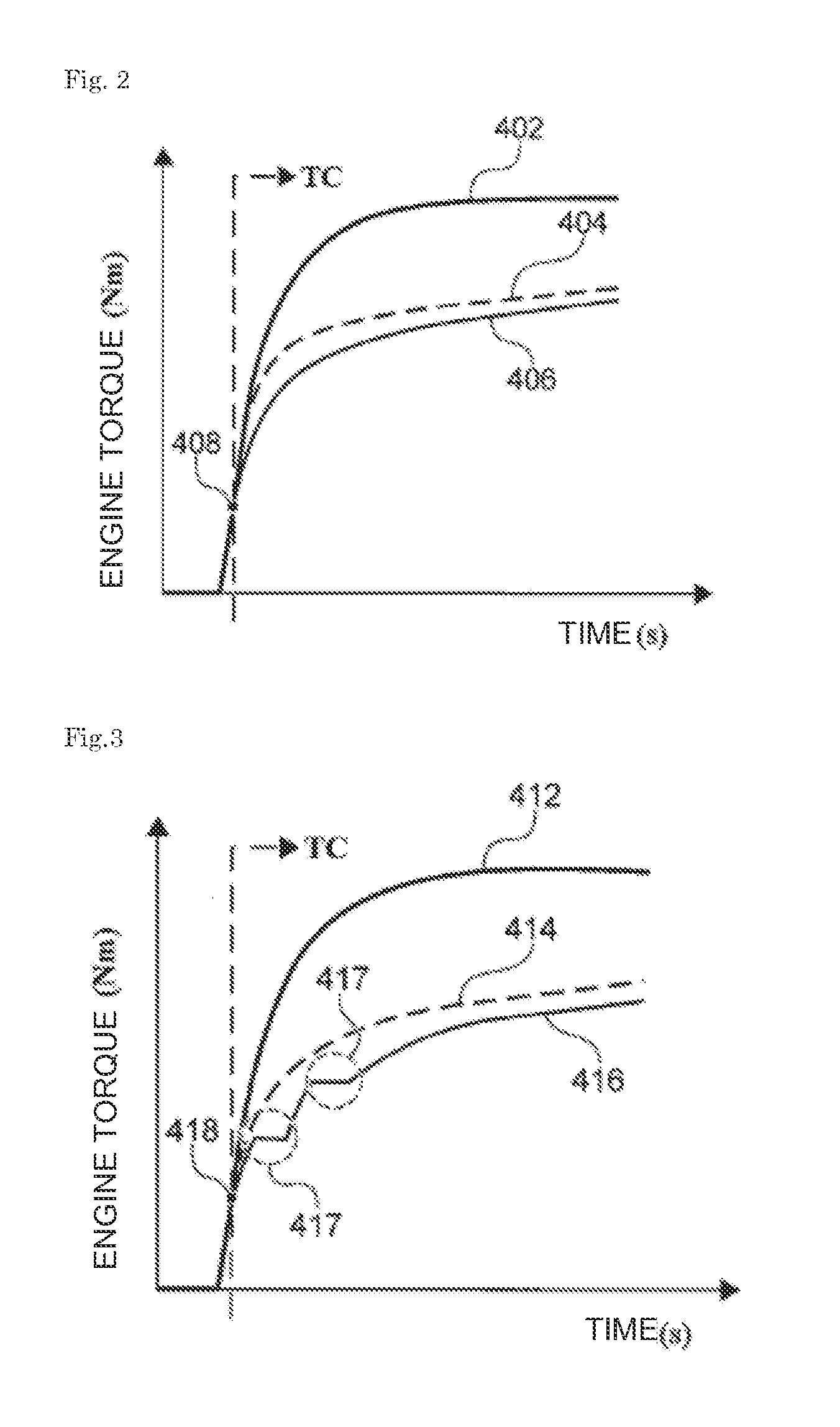
[0032]FIG. 2 shows a first example of control by the torque control apparatus according to the embodiment. In FIG. 2, the vertical axis represents the engine torque (Nm) and the horizontal axis represents an elapse of time (s).
[0033]It is assumed that a driver request torque 402 requested by the driver changes as shown in FIG. 2. For example, when the accelerator pedal position is greatly shifted suddenly from the stop state, the driver request torque 402 sharply rises as shown in FIG. 2.
[0034]The detection unit 310 obtains the change ratio or change amount of the driver request torque 402 by performing the time differentiation of the driver request torque 402. When the obtained change ratio or change amount of the driver request torque 402 becomes larger than a preset threshold, the detection unit 310 detects a state in which the front wheel of the motorcycle is likely to be lifted up. That is, the fact that the change ratio or change amount of the driver request torque 402 is larg...
second example
[0038]Next, a second example of control by the torque control apparatus according to the embodiment will be described. FIG. 3 shows the second example of control by the torque control apparatus according to the embodiment. In FIG. 3, the vertical axis represents the engine torque (Nm) and the horizontal axis represents an elapse of time (s).
[0039]It is assumed that a driver request torque 412 requested by the driver changes as shown in FIG. 3. For example, when the accelerator pedal position is greatly shifted suddenly from the stop state, the driver request torque 412 sharply rises as shown in FIG. 3. The driver request torque 412 in FIG. 3 corresponds to the driver request torque 402 in FIG. 2. In FIG. 3, it is assumed that a state in which the front wheel of the motorcycle is likely to be lifted up is detected at point 418, as in the first example.
[0040]In the second example, the detection unit 310 determines whether the acceleration of the vehicle body or the wheel 240 of the mo...
third example
[0044]Next, a third example of control by the torque control apparatus according to the embodiment will be described. FIG. 4 shows the third example of control by the torque control apparatus according to the embodiment. In FIG. 4, the vertical axis represents the engine torque (Nm) and the horizontal axis represents an elapse of time (s).
[0045]It is assumed that a driver request torque 422 requested by the driver changes as shown in FIG. 4. For example, when the accelerator pedal position is greatly shifted suddenly from the stop state, the driver request torque 422 sharply rises as shown in FIG. 4. The driver request torque 422 in FIG. 4 corresponds to the driver request torque 402 in FIG. 2. In FIG. 4, it is assumed that a state in which the front wheel of the motorcycle is likely to be lifted up is detected at point 428, as in the first example.
[0046]In the third example, the output unit 320 restricts (corrects the timing) or prohibits a control start point 428 or corrects a req...
PUM
Abstract
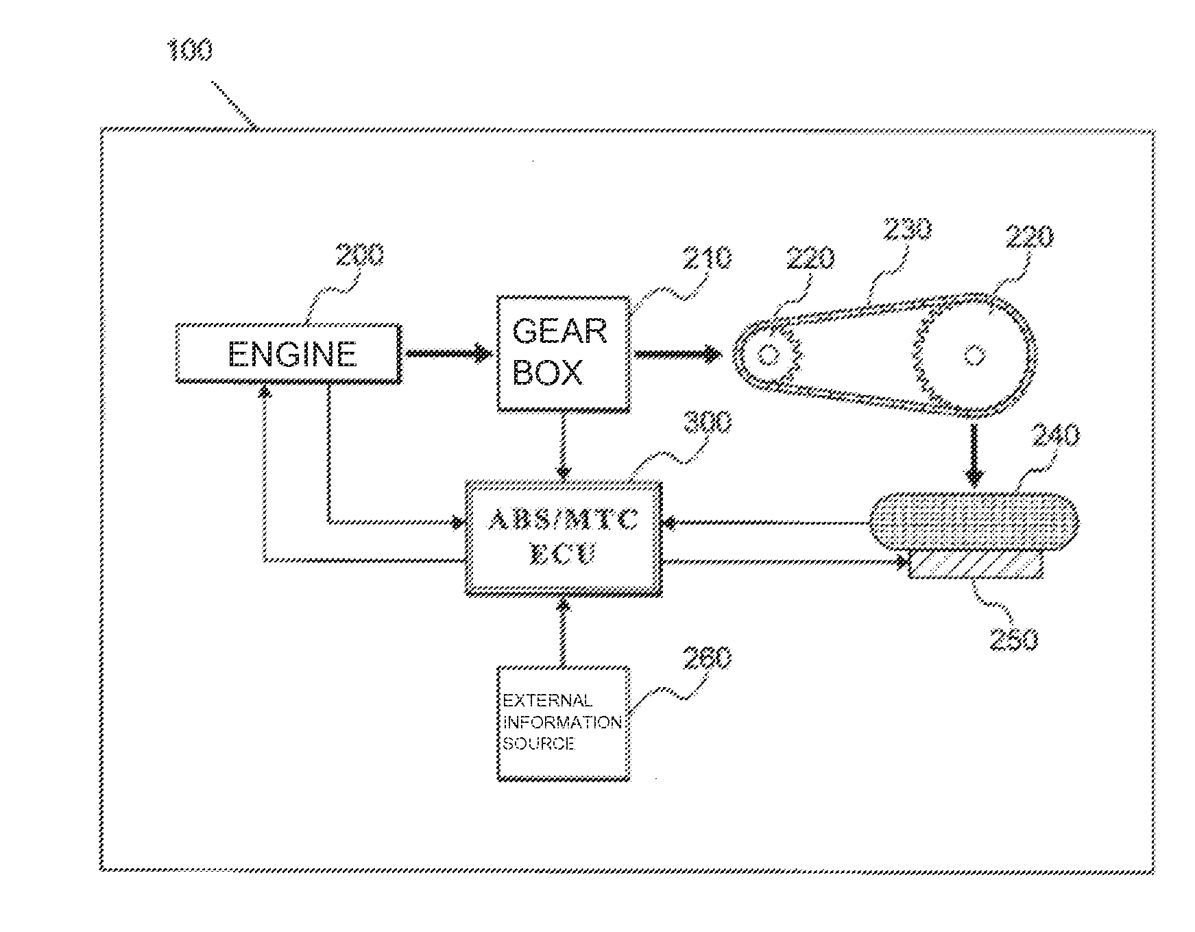
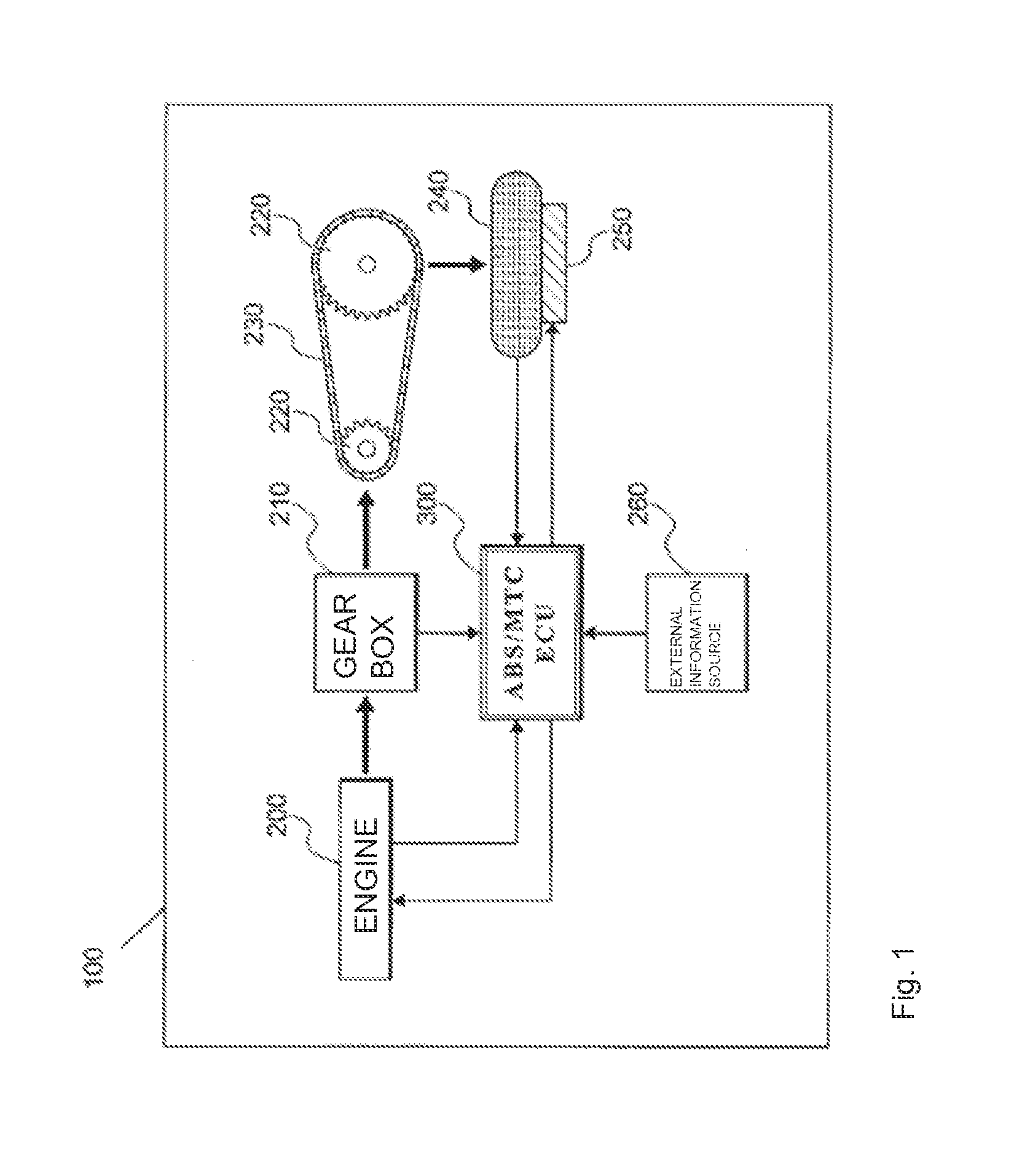
To suppress occurrence of a wheelie of a motorcycle.A torque control apparatus includes a the detection unit that detects a state in which the front wheel of the motorcycle is likely to be lifted up based on at least one of engine information of the motorcycle, accelerator operation information of the driver of the motorcycle, and information of the vehicle body or wheel of the motorcycle. The torque control apparatus further includes an output unit that, when the detection unit detects the state in which the front wheel is likely to be lifted up, outputs a torque smaller than a request torque of the driver as a request torque for an the engine of the motorcycle or outputs the difference between the request torque of the driver and a torque smaller than the request torque of the driver as a brake torque.
Description
BACKGROUND OF THE INVENTION[0001]The present invention relates to a torque control apparatus.[0002]Conventionally, a traction control system (TCS) is known in control of a vehicle such as an automobile or a motorcycle. A TCS performs control by detecting the spin-up (idle running) of the drive wheel of the vehicle and calculating the engine power (torque) for suppressing the spin-up, so that a driving wheel can efficiently transfer a force to a road surface.[0003]Although there are many types of control methods using a TCS, slip control is known as a typical method. This slip control is a control method that determines the desired speed (target speed) of a drive wheel, reduces the engine power (torque) if the actual speed of the drive wheel is larger than the target speed, and increases the engine power (torque) if the actual speed of the drive wheel is smaller than the target speed. More specifically, PID (Proportional Integral Derivative) control is performed on the deviation betw...
Claims
Application Information
Patent Timeline
Application Date:The date an application was filed.
Publication Date:The date a patent or application was officially published.
First Publication Date:The earliest publication date of a patent with the same application number.
Issue Date:Publication date of the patent grant document.
PCT Entry Date:The Entry date of PCT National Phase.
Estimated Expiry Date:The statutory expiry date of a patent right according to the Patent Law, and it is the longest term of protection that the patent right can achieve without the termination of the patent right due to other reasons(Term extension factor has been taken into account ).
Invalid Date:Actual expiry date is based on effective date or publication date of legal transaction data of invalid patent.

