Dispenser with a reservoir comprising a divider or a porous material

Active Publication Date: 2016-05-26
PLASTIPAK BAWT S A R L
View PDF5 Cites 5 Cited by
  • Summary
  • Abstract
  • Description
  • Claims
  • Application Information

AI Technical Summary

Benefits of technology

[0056]The divider may not need to move, and thus the divider may be immovable within the dispenser. It may be fixed in position, preferably near to the downstream end of the dispenser with a small chamber formed between the divider and base of the dispenser. A diptube may pass through the divider and into the chamber which would contain the fluid to be dispensed. Fluid would be able to pass through or around the divider to replace any fluid dispensed. The rate that the fluid could enter the chamber would be comparable but greate

Problems solved by technology

Some products like foods can go off and others like shaving gel can expand and become either unusable or unstable.
This also prevents accidental loss of the air or propellant when the device is used and this can be a problem.
The bags are often made of up to 4 different layers of material so as to keep the propellant and fluid apart and they are relatively expensive and the assembly process is generally expensive and complicated.
One disadvantage is that they cannot be used with d

Method used


Image

  • Dispenser with a reservoir comprising a divider or a porous material
  • Dispenser with a reservoir comprising a divider or a porous material
  • Dispenser with a reservoir comprising a divider or a porous material

Examples


Embodiment Construction

[0061]Further aspects and features of the invention will be understood from the following description of a number of embodiments of the invention, which are provided by way of example only, with reference to the accompanying drawings, in which:

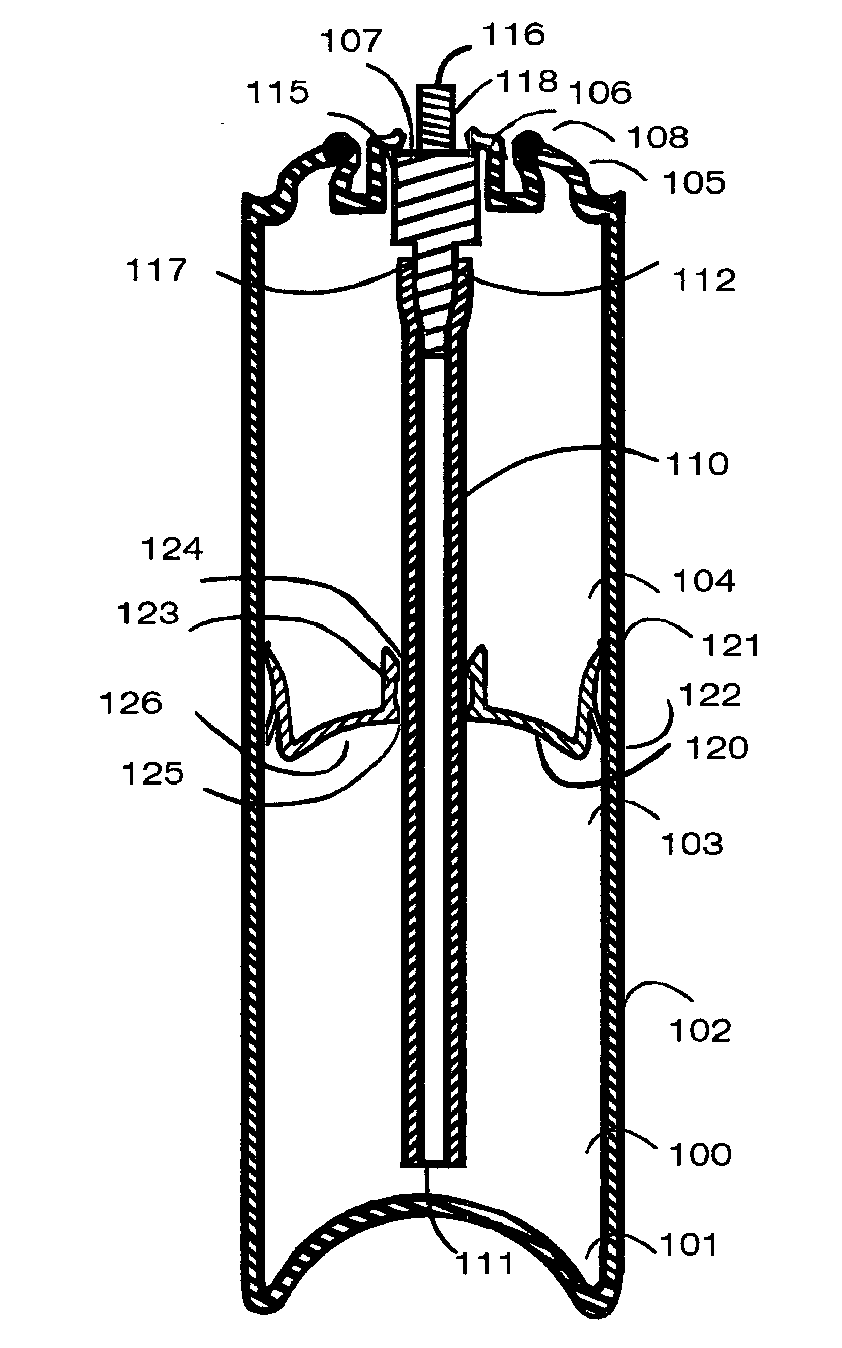
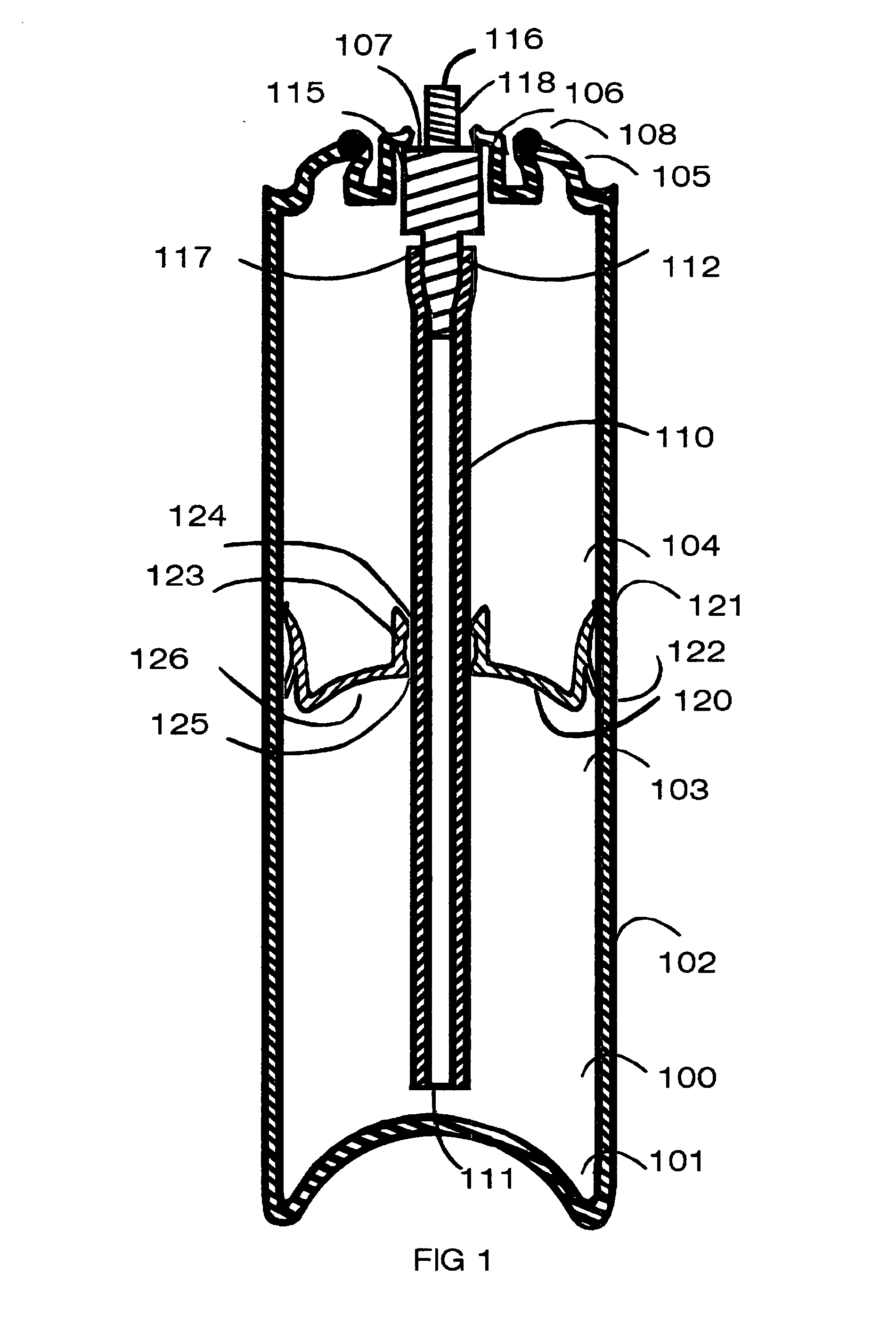
[0062]FIG. 1 is a cross-sectional view though a dispenser of the invention in the form of an aerosol canister with divider of the invention inside and a diptube.

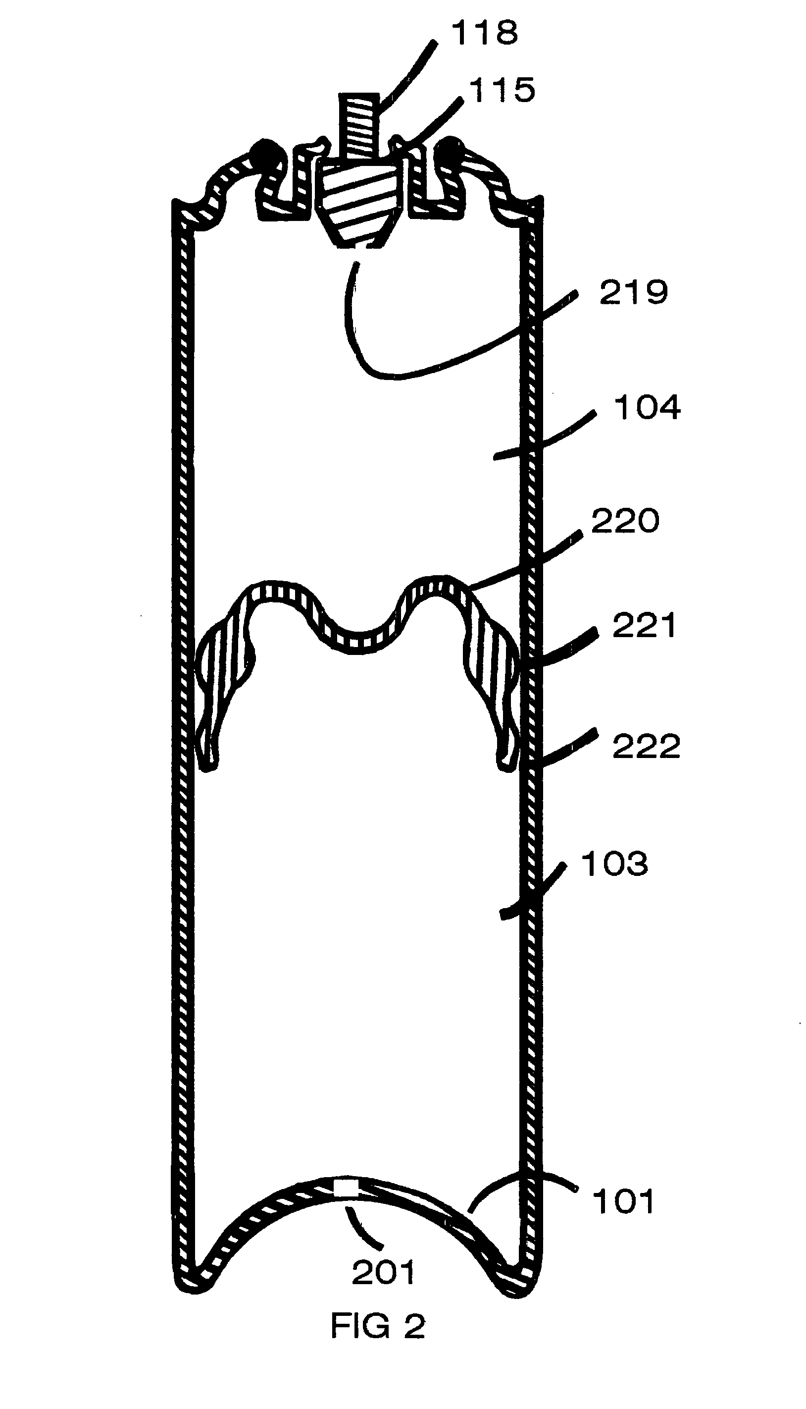
[0063]FIG. 2 is a view similar to that of FIG. 1 but showing the version with no diptube.

[0064]FIG. 3 is a cross-sectional view though a pump dispenser of the invention with a divider of the invention in the form of a foam plate inside.

[0065]FIG. 4 is a cross-sectional view though a dispenser of the invention in the form of an aerosol canister with foam plug divider of the invention inside.

[0066]FIG. 5 is a cross-sectional view though a dispenser of the invention comprising a trigger with a foam rod divider inside.

[0067]FIG. 6 is a cross-sectional view though a dispenser of the inventi...


PUM

PropertyMeasurementUnit
Timeaaaaaaaaaa
Pore sizeaaaaaaaaaa
Pore sizeaaaaaaaaaa

Abstract

A pressurized dispenser includes a base and a peripheral wall having an open end sealed by a dispensing element comprising a dip-tube, a fluid reservoir in contact with the dip-tube for reducing the compressed gas lost from the pressurized dispenser, a compressed gas and a dispensing liquid. In embodiments, a majority of the fluid reservoir may be located outside of the dip-tube, and the fluid reservoir may include a porous material, arranged in use to hold a volume of the dispensing liquid. Such porous material may be configured so that, in use, at least a portion of any compressed gas in the reservoir can be displaced by the liquid, ejecting such portion of the compressed gas into the dispenser. In embodiments, the dispensing element may be configured to dispense dispensing liquid continuously for at least 0.5 seconds, upon actuation of the dispensing element.

Description

TECHNICAL FIELD OF THE INVENTION[0001]This invention relates to dispensers having dividers or fluid reservoirs therein arranged to at least partially prevent gas or air in the dispensers from being ejected through dip tubes in the dispenser. The invention further relates to dividers for use in fluid dispensers, which dividers at least partially prevent mixing of gas / air and fluid in a dispenser, in use.BACKGROUND TO THE INVENTION[0002]It is known to provide both pressurized fluid dispensers, and non-pressurized fluid dispensers which dispense fluid through a nozzle arrangement, and which may include a dip tube connected to the nozzle arrangement, through which fluid is dispensed.[0003]Nozzle arrangements are commonly used to facilitate the dispensing of various fluids from containers or vessels. For instance, nozzle arrangements are commonly fitted to pressurized fluid filled vessels or containers, such as an aerosol canister, to provide a means by which fluid stored in the vessel o...

Claims


Application Information

Patent Timeline
IPC IPC(8): B65D83/60B65B31/00B65D83/14B65D83/32B65D83/44B05B15/30
CPCB65D83/60B65D83/32B65B31/003B65D83/754B65D83/44B05B11/0059B65D83/36B65D83/42B65D83/425B65D83/64B65D83/646B05B15/30B05B11/029B05B11/028
Inventor LAIDLER, KEITHRODD, TIMOTHY
Owner PLASTIPAK BAWT S A R L
Why Eureka
Try Eureka