Image display apparatus

a technology of image display and display device, which is applied in the direction of optics, electrical devices, instruments, etc., can solve the problems of increased nose load, loss of weight balance of image display apparatus, and worse feeling of use, so as to improve visual recognition of image and reliably visual recognition the effect of imag

Active Publication Date: 2016-05-26
SEIKO EPSON CORP
View PDF6 Cites 5 Cited by
  • Summary
  • Abstract
  • Description
  • Claims
  • Application Information

AI Technical Summary

Benefits of technology

[0050]According to the second aspect, the position of the display unit may be adjusted so that the display surface may be nearly orthogonal to the line of sight of the observer by rotation of the supporting part, and thereby, the position of the display unit may be adjusted to the position in which the image is easily visually recognized in response to the line of sight of the observer. Therefore, visual recognition of the image may be improved. In addition, as described above, the display unit may be placed in response to the direction of the line of sight in which the observer may be relaxed, and thereby, the observer may reliably visually recognize the image under a relaxed condition.

Problems solved by technology

Accordingly, when the virtual image display apparatus is used over a long period of time, there is a problem that the load on the nose increases and the feeling of use becomes worse.
Here, when the imaging unit is located in the display unit, it is considered that the weight balance of the image display apparatus is lost due to the load of the imaging unit.
Further, there is a problem of a bad appearance if the cable extends from the display unit to the outside.
Specifically, when the line of sight is directed to the upper side including the orthogonal direction, it is necessary to apply more tension to the extraocular muscle for changing the line of sight than that when the line of sight is directed to the lower side than the orthogonal direction, and fatigue of the extraocular muscle is easily caused.

Method used


Image

  • Image display apparatus
  • Image display apparatus
  • Image display apparatus

Examples


first embodiment

Advantages of First Embodiment

[0125]According to the above described virtual image display apparatus 1 of the embodiment, the following advantages are obtained.

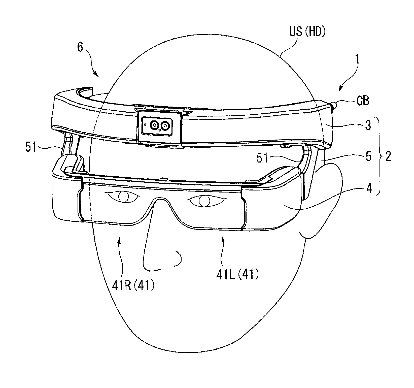
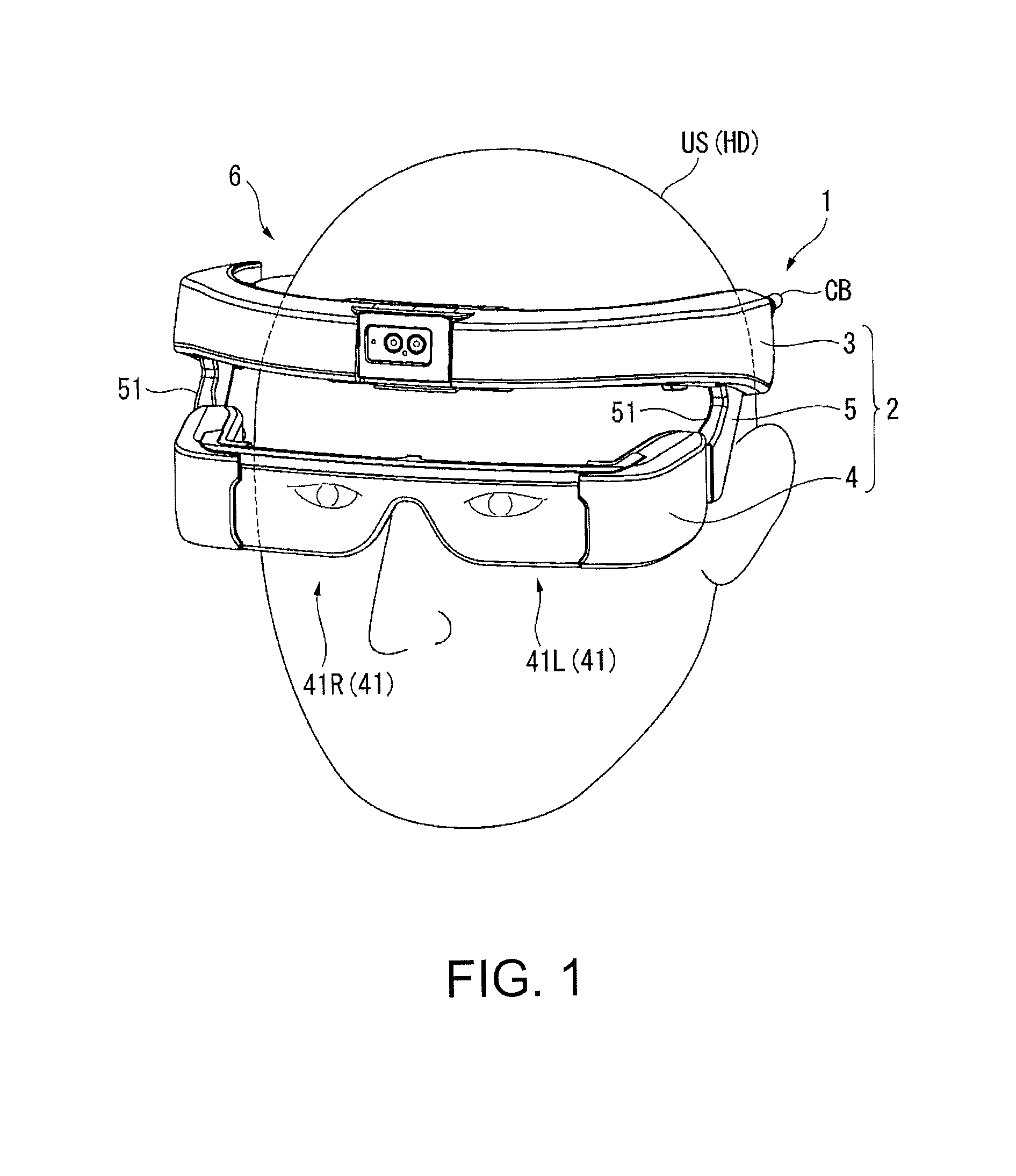
[0126]The headband part 3 as the frame along the head HD of the observer US is fixed to the position in which the virtual image displayed by the display unit 4 connected to the headband part 3 via the arms 51 of the supporting part 5 can be visually recognized by the observer US. Thereby, the headband part 3 is placed along the head HD (forehead) and fixed, and the load of the virtual image display apparatus 1 on the nose and the ears of the observer may be suppressed. Therefore, the load on the observer US in use of the virtual image display apparatus 1 may be reduced and the feeling of use and the feeling of wearing may be improved.

[0127]The respective arms 51 of the supporting part 5 are rotatable around the connection parts to the headband part 3, and thereby, the position and the angle of the display unit 4 with respect ...

second embodiment

Advantages of Second Embodiment

[0180]According to the above described virtual image display apparatus 1A of the embodiment, the same advantages as those of the virtual image display apparatus 1 may be obtained, and further, the following advantages may be obtained.

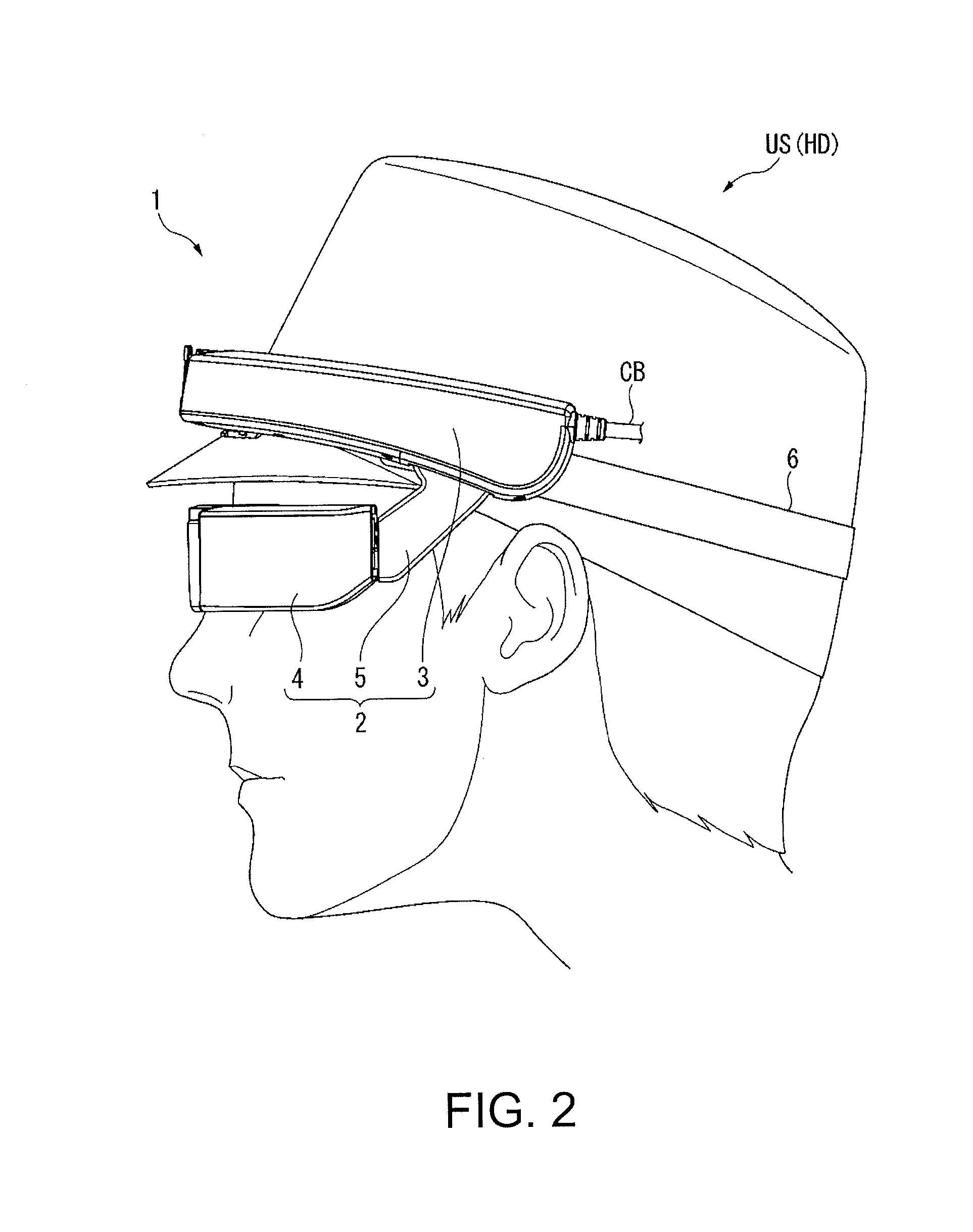
[0181]Here, as described above, a human is more comfortable to direct the line of sight to the lower side than an orthogonal direction than to direct the line of sight to the upper side including the orthogonal direction (Z-direction) with respect to the axial direction of the head HD (Y-direction).

[0182]On the other hand, the display unit 4 is placed so that, when the head HD is seen along the direction orthogonal to the Y-direction and the Z-direction (X-direction), the virtual image surfaces on which the images are visually recognized may be nearly orthogonal to the lines of sight L2 as virtual lines inclined downward at a predetermined angle with respect to the Y-direction and the Z-direction.

[0183]According to the con...


PUM


Abstract

An image display apparatus includes a frame along a head of an observer, a display unit that displays an image that can be visually recognized by the observer, and a supporting part attached to the frame and supporting the display unit, wherein the frame is fixed to a position in which the image displayed by the display unit connected to the frame via the supporting part is visually recognized by the observer.

Description

BACKGROUND[0001]1. Technical Field[0002]The present invention relates to an image display apparatus.[0003]2. Related Art[0004]In related art, virtual image display apparatuses including HMDs (Head Mounted Displays) worn on heads of observers have been known (for example, see Patent Document 1 (JP-A-2014-186201)).[0005]The virtual image display apparatus disclosed in Patent Document 1 is formed as a see-through HMD including a first image forming main body unit and a second image forming main body unit respectively provided on right and left of the observer, and light guiding members that respectively guide image lights formed by these image forming main body units to the right eye and the left eye of the observer. Further, the virtual image display apparatus includes a frame part having a nose pad member to be in contact with the nose of the observer, and temple portions to be in contact with the temple areas of the observer. The virtual image display apparatus is worn so that the r...

Claims


Application Information

Patent Timeline
Patent Type & Authority Applications(United States)
IPC IPC(8): G02B27/01G02C3/02H04N13/239
CPCG02B2027/0152G02B2027/0159G02B2027/0138G02B2027/014G02B2027/0178G02B27/0176G02B27/0172G02C3/02G02B2027/0132G02B27/017G02B2027/0169G02B2027/0154H04N13/239H04N13/344H04N13/349
Inventor FUJISHIRO, TAKESHI
Owner SEIKO EPSON CORP
Why Eureka
Try Eureka