
Pressing sensor, touch sensor, pressing sensor-equipped display panel, and touch sensor-equipped display panel

a technology of sensor and display panel, which is applied in the field of pressing sensor, touch sensor, pressing touch sensor equipped display panel, etc., can solve the problems of not being able to achieve decoloration and not being able to make the transmittance at each wavelength in the visible light range substantially uniform, etc., and achieve the effect of substantially uniform transmittan

Inactive Publication Date: 2016-05-26
MURATA MFG CO LTD
View PDF10 Cites 4 Cited by
  • Summary
  • Abstract
  • Description
  • Claims
  • Application Information

AI Technical Summary

Benefits of technology

The present invention is related to a pressing sensor that uses an organic piezoelectric material made of polylactic acid as the main component. This configuration helps increase the transparency of the sensor and cancels out variations in transmittance caused by the electrified surface. As a result, the sensor can display a uniform color image on the surface and provide accurate response to pressure.

Problems solved by technology

However, according to the configuration described in Patent Literature 1, different color tints are only provided, and therefore it is not possible to achieve decoloring, i.e., it is not possible to make the transmittance at each wavelength in a visible light range substantially uniform.

Method used


Image

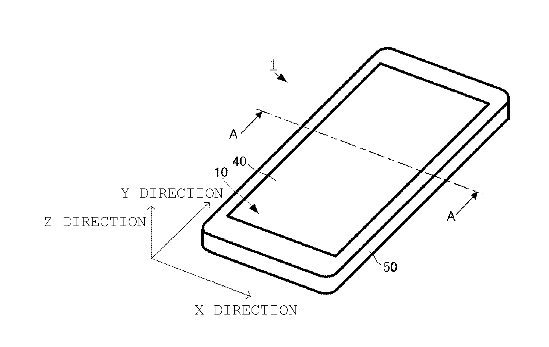
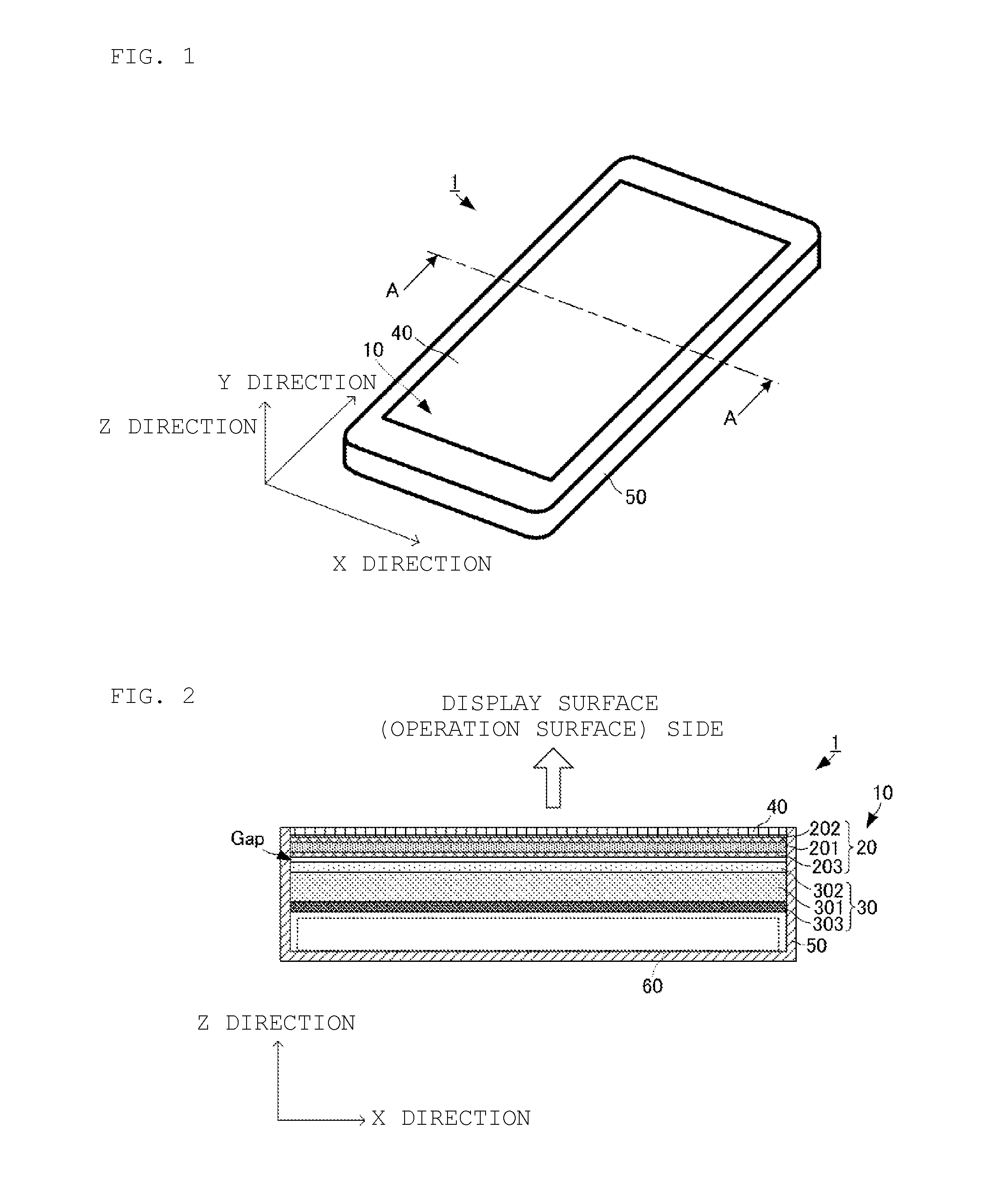
  • Pressing sensor, touch sensor, pressing sensor-equipped display panel, and touch sensor-equipped display panel
  • Pressing sensor, touch sensor, pressing sensor-equipped display panel, and touch sensor-equipped display panel
  • Pressing sensor, touch sensor, pressing sensor-equipped display panel, and touch sensor-equipped display panel

Examples


first embodiment

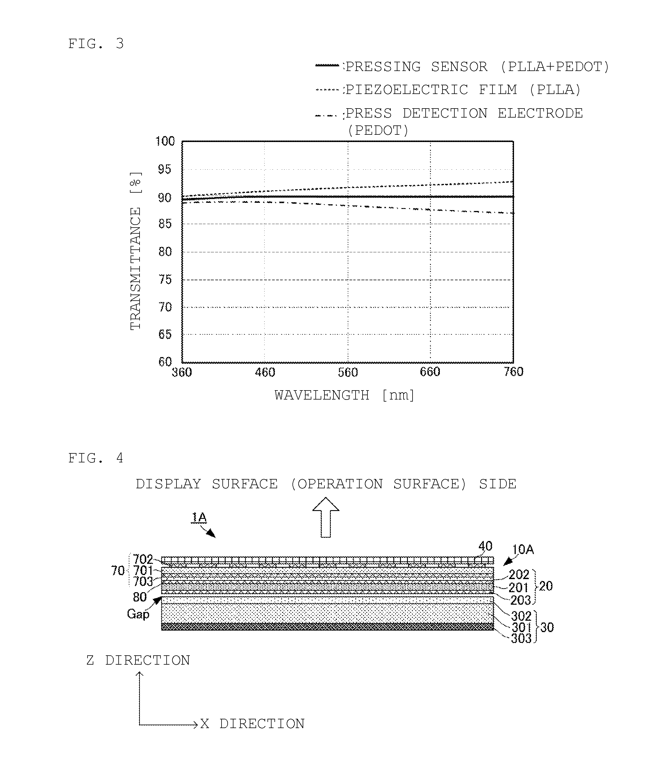
[0045]In this regard, by using the configuration according to the present embodiment, it is possible to make substantially uniform the transmittance at each wavelength in the visible light range of the pressing sensor 20. FIG. 3 is a graph illustrating spectral transmittance characteristics of the pressing sensor according to the present invention.

[0046]As indicated by a broken line in FIG. 3, the piezoelectric film 201 has a higher transmittance of a long wavelength than a transmittance of a short wavelength in the visible light range. Further, as the wavelength becomes longer, the transmittance becomes higher. Hence, light having transmitted only through the piezoelectric film 201 has a yellow tinge.

[0047]Meanwhile, as indicated by a dashed-dotted line in FIG. 3, the polythiophene electrode has a higher transmittance of a short wavelength than a transmittance of a long wavelength in the visible light range. Further, as the wavelength becomes shorter, the transmittance becomes high...

second embodiment

[0060]In this regard, by using the configuration according to the present embodiment, it is possible to make substantially uniform the transmittance at each wavelength in the visible light range of the touch sensor (pressing sensor 20+position detecting sensor 70). FIG. 5 is a graph illustrating spectral transmittance characteristics of the touch sensor according to the present invention.

[0061]Meanwhile, as indicated by a dashed-dotted line in FIG. 5, the position detecting sensor 70 has the electrodes 702 and 703 made of ITO, and therefore has a lower transmittance of a short wavelength than a transmittance of a long wavelength in the visible light range. Further, as the wavelength becomes shorter, the transmittance becomes lower. Further, near a range of the shortest wavelength (360 nm) and a range of the longest wavelength (760 nm) in the visible light range, transmittances significantly differ. Hence, light having transmitted only through the position detecting sensor 70 has a s...


PUM


Abstract

A pressing sensor-equipped display panel that includes a pressing sensor and a display panel. The pressing sensor is arranged between a protecting member which composes an operation surface and the display panel. The pressing sensor includes a piezoelectric film which is made of polylactic acid which is an organic piezoelectric material. Electrodes are formed on both principal surfaces of the piezoelectric film. At least one of the electrodes is made of a polythiophene material. Display image formation light which has been emitted from the display panel and been incident on the pressing sensor transmits through the piezoelectric film and the electrodes. In this regard, a variation of a transmittance of each wavelength of the piezoelectric film, and a variation of a transmittance of each wavelength of an electrode made of the polythiophene material cancel each other.

Description

CROSS REFERENCE TO RELATED APPPLICATIONS[0001]The present application is a continuation of International application No. PCT / JP2014 / 074352, filed Sep. 16, 2014, which claims priority to Japanese Patent Application No. 2013-191792, filed Sep. 17, 2013, the entire contents of each of which are incorporated herein by reference.FIELD OF THE INVENTION[0002]The present invention relates to a pressing sensor which can receive an input by a pressing operation when a finger or the like performs an operation on a display screen, a touch sensor which includes the pressing sensor, and a pressing sensor-equipped or touch sensor-equipped display panel.BACKGROUND OF THE INVENTION[0003]Conventionally, various electronic devices which include a thin display panel such as a liquid crystal display and can receive an input by an operation via a display surface have been devised. In such an electronic device, a touch sensor which receives an input by the operation is arranged on a surface of the display...

Claims


Application Information

Patent Timeline
Patent Type & Authority Applications(United States)
IPC IPC(8): G06F3/041
CPCG06F3/0414G06F2203/04106G06F3/0412G06F3/0447
Inventor KANO, HIDEKAZUINOUE, TAKAFUMIANDO, MASAMICHI
Owner MURATA MFG CO LTD
Learn More