Shielded conductive path

a shielded conductive and path technology, applied in the direction of insulated conductors, cables, conductors, etc., can solve the problems of coating of electric wire bundles, and achieve the effect of preventing water infiltration

Active Publication Date: 2016-05-26
SUMITOMO WIRING SYST LTD
View PDF5 Cites 10 Cited by
  • Summary
  • Abstract
  • Description
  • Claims
  • Application Information

AI Technical Summary

Benefits of technology

[0007]A filler stops water in a liquidtight manner in a void between the outer circumference of the electric wire bundle and the inner circumference of the heat-shrinkable tube. A tubular waterstopping member covers a region of the braided wire between the heat-shrinkable tube and the shield pipe, and stops water. Accordingly, it is possible to prevent infiltration of water between the outer circumference of the electric wire bundle and the inner circumference of the shield pipe.

Problems solved by technology

If water infiltrates into the shield pipe, there is a risk that frozen infiltrating water damages the coating of the electric wire bundle during vehicle vibration, and therefore, a countermeasure is needed.

Method used


Image

  • Shielded conductive path
  • Shielded conductive path
  • Shielded conductive path

Examples


embodiment 1

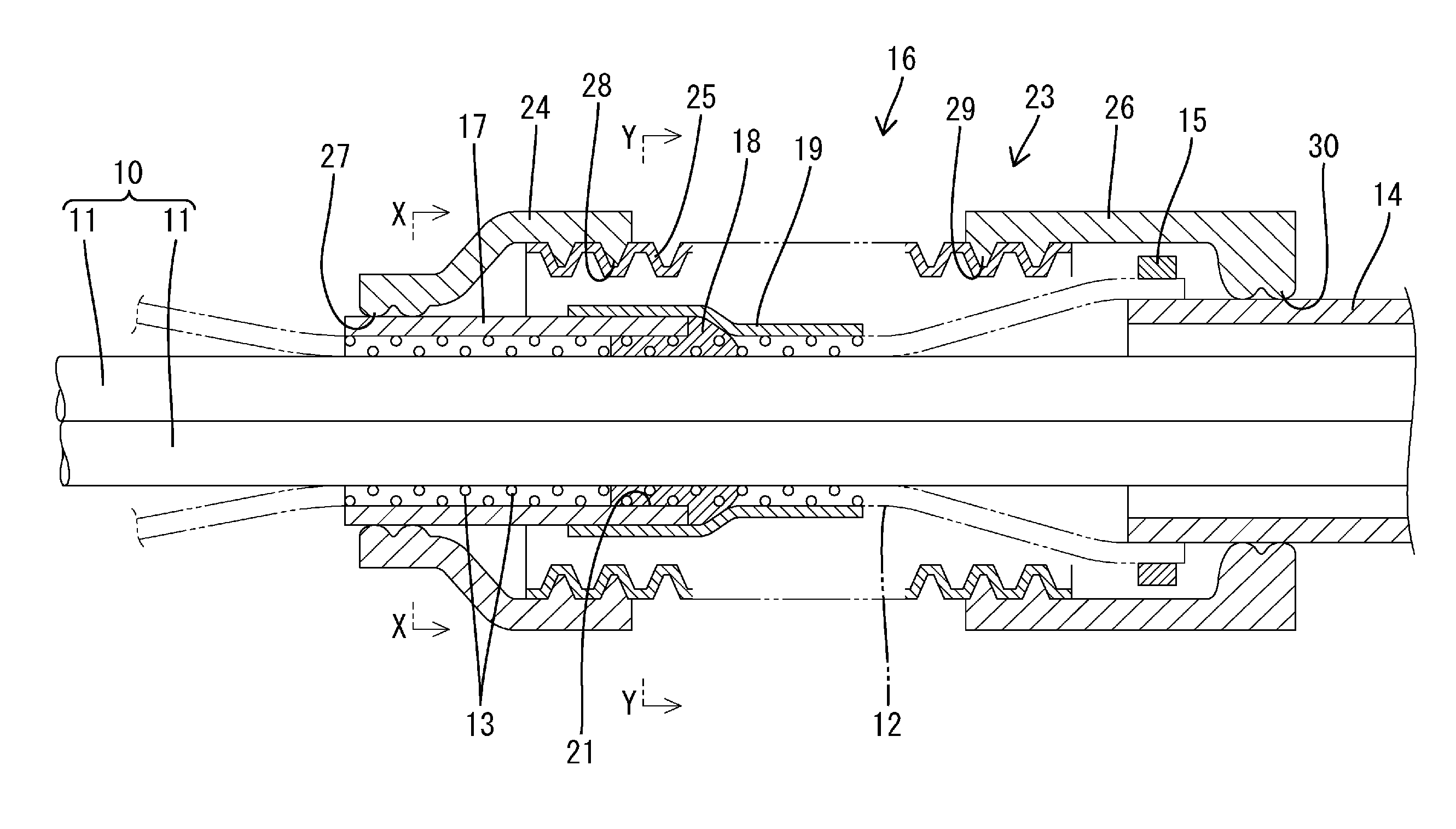
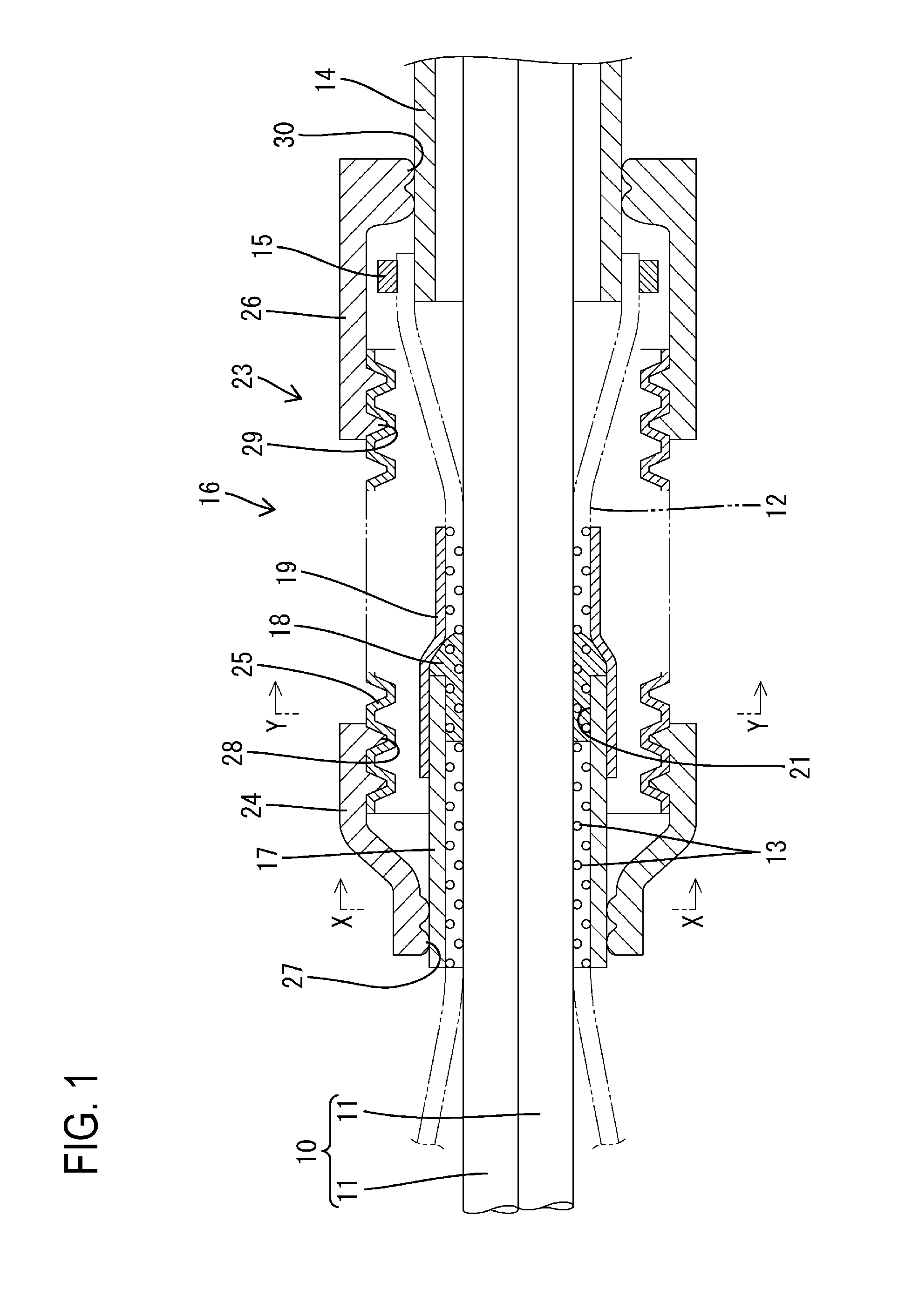
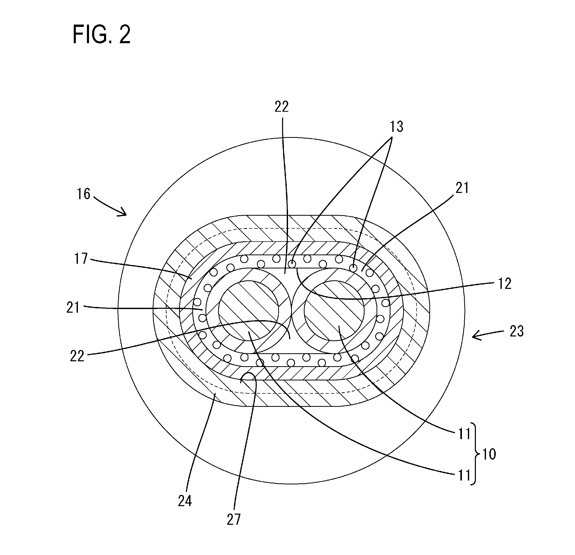
[0014]Hereinafter, Embodiment 1, in which the present application is embodied, will be described with reference to FIGS. 1 to 3. The shielded conductive path of this embodiment includes an electric wire bundle 10, a tubular braided wire 12 as a shield means, a shield pipe 14 also serving as a shield means, and a waterproofing means 16. It should be noted that in terms of a front-rear direction in the description below, the left side in FIG. 1 is defined as the “front side” for the sake of convenience.

[0015]The electric wire bundle 10 is obtained by bundling two coated electric wires 11 such that they are in parallel with and adjacent to each other. The braided wire 12 is obtained by braiding a plurality of wires 13 made of a metal material such as copper into a tubular shape. The rear end portion of the braided wire 12 covers the front end portion of the shield pipe 14 and is secured thereto by a crimp ring 15 so that electrical conduction can be established. The shield pipe 14 is m...


PUM

PropertyMeasurementUnit
conductiveaaaaaaaaaa
circumferenceaaaaaaaaaa
heat-shrinkableaaaaaaaaaa

Abstract

Infiltration of water into a shield pipe is prevented. A shielded conductive path includes a tubular braided wire, a shield pipe connected to the braided wire, an electric wire bundle inserted into the braided wire and the shield pipe, a heat-shrinkable tube that is disposed so as to cover the braided wire and is thermally shrunk to bring the braided wire into intimate contact with an outer circumference of the electric wire bundle, a filler (18) with which voids between the electric wire bundle and the heat-shrinkable tube are filled, and a tubular waterstopping member that covers a region of the braided wire between the heat-shrinkable tube and the shield pipe in a state in which two end portions of the tubular waterstopping member are in intimate contact with an outer circumferential surface of the heat-shrinkable tube and the outer circumferential surface of the shield pipe in a liquidtight manner.

Description

CROSS-REFERENCE TO RELATED APPLICATIONS[0001]This application is a National Stage application of International Application No. PCT / JP2014 / 068896, filed on Jul. 16, 2014, and claims priority to Japanese Patent Application No. 2013-161367 filed on Aug. 2, 2013, the disclosures of both of which are incorporated herein by reference in their entireties.TECHNICAL FIELD[0002]Embodiments of the present application relate to a shielded conductive path having waterproof performance.BACKGROUND[0003]JP 2010-040396A discloses a shielded conductive path of a form in which a tubular braided wire and a shield pipe are connected to each other and an electric wire bundle is inserted into this braided wire and the shield pipe. A region of the shielded conductive path that is covered with the braided wire can be freely bent and routed.SUMMARY OF THE INVENTION[0004]The above shielded conductive path has a structure in which water can infiltrate between the outer circumference of the electric wire bundle...

Claims


Application Information

Patent Timeline
Patent Type & Authority Applications(United States)
IPC IPC(8): H01B7/282H02G3/04
CPCH01B7/2825H02G3/0487H02G3/0468H02G3/06Y02A30/14
Inventor HAGI, MASAHIRO
Owner SUMITOMO WIRING SYST LTD
Why Eureka
Try Eureka