Wireless communication method for enhancing transmission efficiency through separating transmission interval in wireless local area network (WLAN) system

a wireless local area network and wireless communication technology, applied in sustainable communication technology, high-level techniques, climate sustainability, etc., can solve the problems of inability to prevent terminals from transmitting ps-, the efficiency of wireless wlan has emerged as an issue in a highly dense environment, etc., to reduce standby time, enhance power saving efficiency, and reduce collision

Active Publication Date: 2016-05-26
ELECTRONICS & TELECOMM RES INST
View PDF6 Cites 8 Cited by
  • Summary
  • Abstract
  • Description
  • Claims
  • Application Information

AI Technical Summary

Benefits of technology

[0027]According to embodiments, it is possible to decrease a collision by distributing transmission intervals of terminals to be uniform across a beacon interval instead of performing transmission at a specific point in time, such as a beacon transmission time. Further, it is possible to reduce a standby time in a wakeup state by data transmission, thereby enhancing the power saving efficiency.
[0028]According to embodiments, it is possible to prevent a degradation in the performance of a high throughput terminal by a legacy terminal by distributing transmission intervals of terminals having different types, for example, a legacy terminal and high throughput terminal in an existing WLAN band such as 2.4 GHz and 5 GHz. Further, it is possible to enhance the performance of the entire WLAN by preventing contention between terminals from increasing in a specific time interval.

Problems solved by technology

Currently, with a rapid increase in the use of the WLAN and the number of wireless terminals, the efficiency of the wireless WLAN has emerged as an issue in a highly dense environment.
However, in the existing frequency band, such as 2.4 GHz or 5 GHz, legacy terminals do not follow a RAW operation and thus, the RAW may be readily introduced.
However, since such beacons are generally used to enhance a network discovery rate and do not have traffic indicator map (TIM) information, it may not be possible to prevent terminals from transmitting PS-polls at a time at a transmission point in time of a beacon.

Method used


Image

  • Wireless communication method for enhancing transmission efficiency through separating transmission interval in wireless local area network (WLAN) system
  • Wireless communication method for enhancing transmission efficiency through separating transmission interval in wireless local area network (WLAN) system
  • Wireless communication method for enhancing transmission efficiency through separating transmission interval in wireless local area network (WLAN) system

Examples


Embodiment Construction

Object

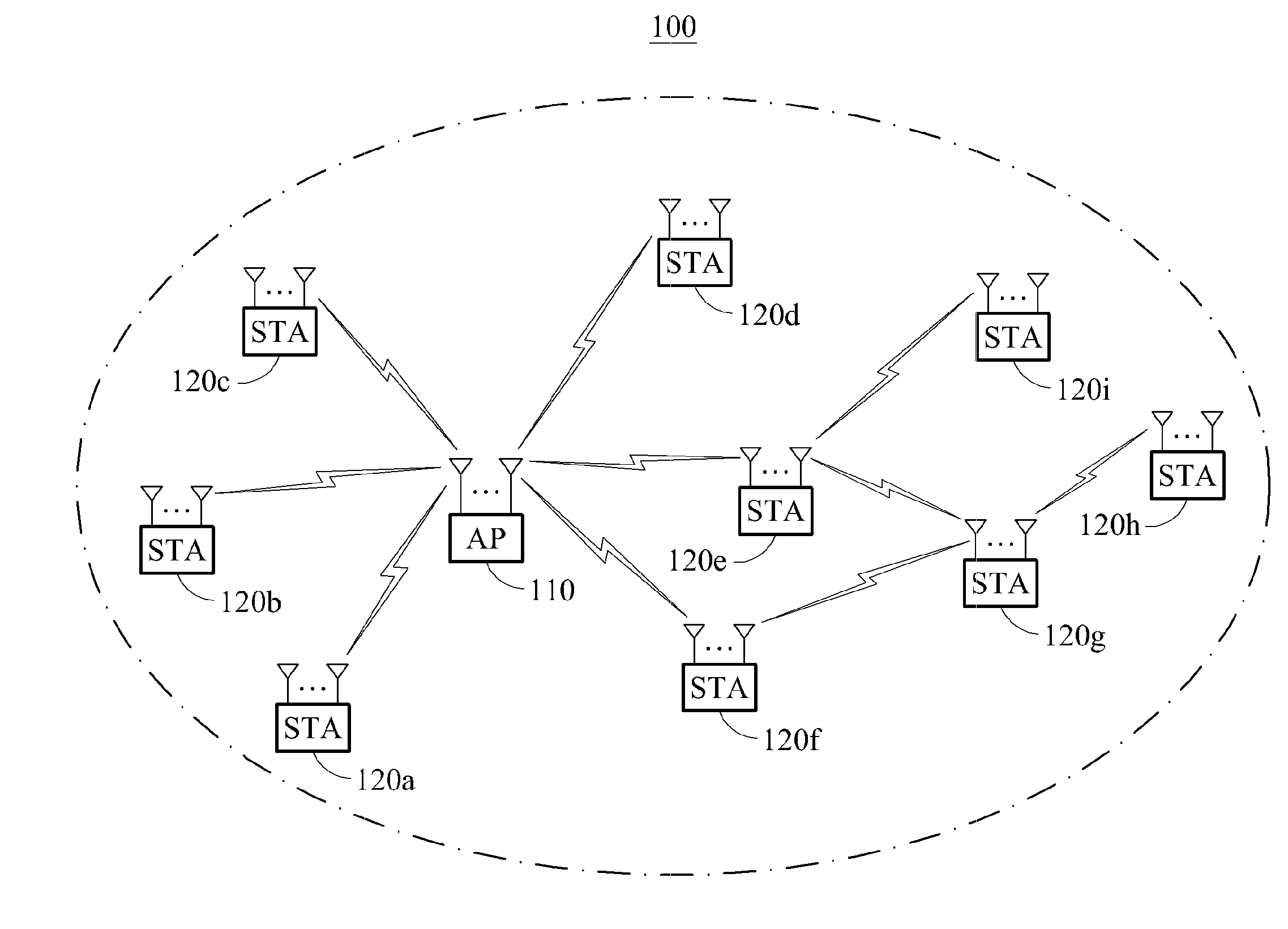
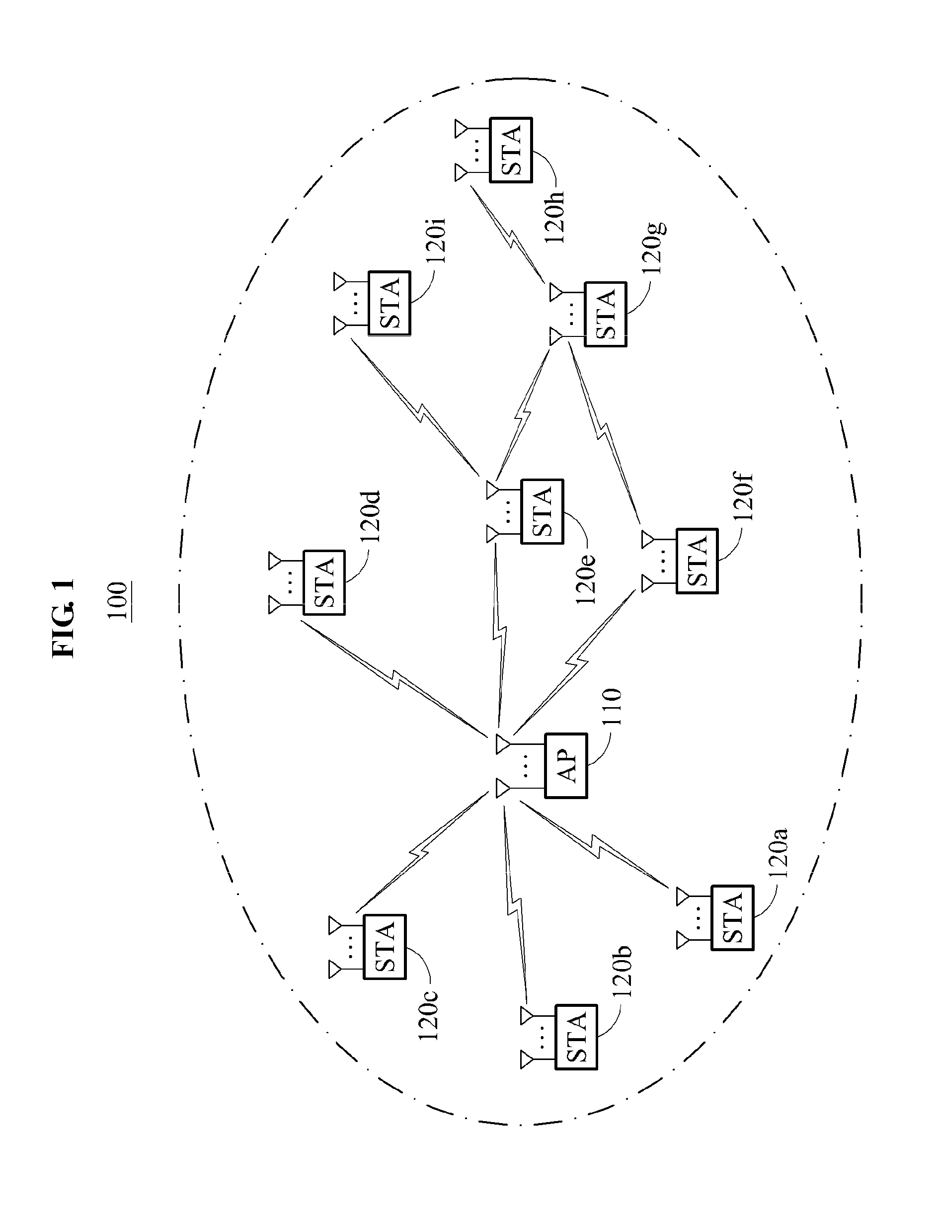
[0008]Embodiments provide a method that may prevent an occurrence of contention by distributing a transmission interval of terminals so that different device types of terminals may perform transmission in different time intervals even in 2.4 GHz and 5 GHz, and may prevent a degradation in the network performance by a legacy terminal by enabling a terminal, such as 11ac terminal and 11ax terminal, to perform transmission in a time interval different from a time interval of the legacy terminal.

[0009]Embodiments also provide a method of enhancing the transmission efficiency by distributing a transmission interval based on a device type that may prevent a degradation in the overall network efficiency and may also prevent contention from occurring at a specific point in time, when a legacy terminal is mixed.

Solution

[0010]According to an aspect, there is provided a wireless communication method performed at an access point, the method including scheduling a transmission time of an e...


PUM


Abstract

Provided is a wireless communication method performed at an access point to enhance the transmission efficiency in a wireless local area network (WLAN) system, the method including scheduling a transmission time of an enhanced traffic indicator map (TIM) frame based on a type of a station, and transmitting a second beacon including the enhanced TIM frame to the station at a point in time aside from a transmission point in time of a first beacon.

Description

TECHNICAL FIELD[0001]Embodiments relate to technology for performing wireless communication by distributing a transmission interval based on a type of a terminal in a wireless local area network (WLAN) system.RELATED ART[0002]In general, a local area network (LAN) that is a near field communication network is divided in a wired LAN and a wireless LAN (WLAN). The WLAN employs a method of performing communication on a network using propagation instead of using a cable. The WLAN has been introduced as an alternative for overcoming difficulties found in installation, maintenance and repair, and movement by cabling. According to an increase in mobile users, a need for the WLAN is also increasing.[0003]The WLAN includes an access point and a station (STA) that is a terminal device. The access point refers to equipment that transmits propagation so that WLAN users present within a transmission distance may connect to the Internet and utilize a network. The access point may serve as a base ...

Claims


Application Information

Patent Timeline
Patent Type & Authority Applications(United States)
IPC IPC(8): H04W72/12H04W52/02
CPCH04W72/1257H04W84/12H04W52/0206H04W48/12H04W74/04Y02D30/70
Inventor LEE, JAE SEUNGKIM, IL GYUPARK, JAE WOOLEE, YU ROCHOI, JEE YON
Owner ELECTRONICS & TELECOMM RES INST
Why Eureka
Try Eureka