Power Supply System Applied to Electrically Powered Vehicle

a technology of power supply system and electrically powered vehicle, applied in the direction of battery/fuel cell control arrangement, electric devices, propulsion by batteries/cells, etc., can solve the problem of achieve the effect of protecting from overheating and not excessively deteriorating vehicle traveling performan

Active Publication Date: 2016-06-02
DENSO CORP
View PDF1 Cites 10 Cited by
  • Summary
  • Abstract
  • Description
  • Claims
  • Application Information

AI Technical Summary

Benefits of technology

[0012]Therefore, a main advantage of the present invention is that, in a power supply system of an electrically powered vehicle configured to include a boost converter for boosting the voltage from a power storage device, the boost converter can be protected from overheating without excessively deteriorating the vehicle traveling performance.
[0013]The foregoing and other objects, features, aspects and advantages of the present invention will become more apparent from the following detailed description of the present invention when taken in conjunction with the accompanying drawings.

Problems solved by technology

However, since the limitation on the current of the boost converter leads to the limitation on the torque in the electric motor for generating vehicle driving force, the vehicle traveling performance is deteriorated.

Method used


Image

  • Power Supply System Applied to Electrically Powered Vehicle
  • Power Supply System Applied to Electrically Powered Vehicle
  • Power Supply System Applied to Electrically Powered Vehicle

Examples


first embodiment

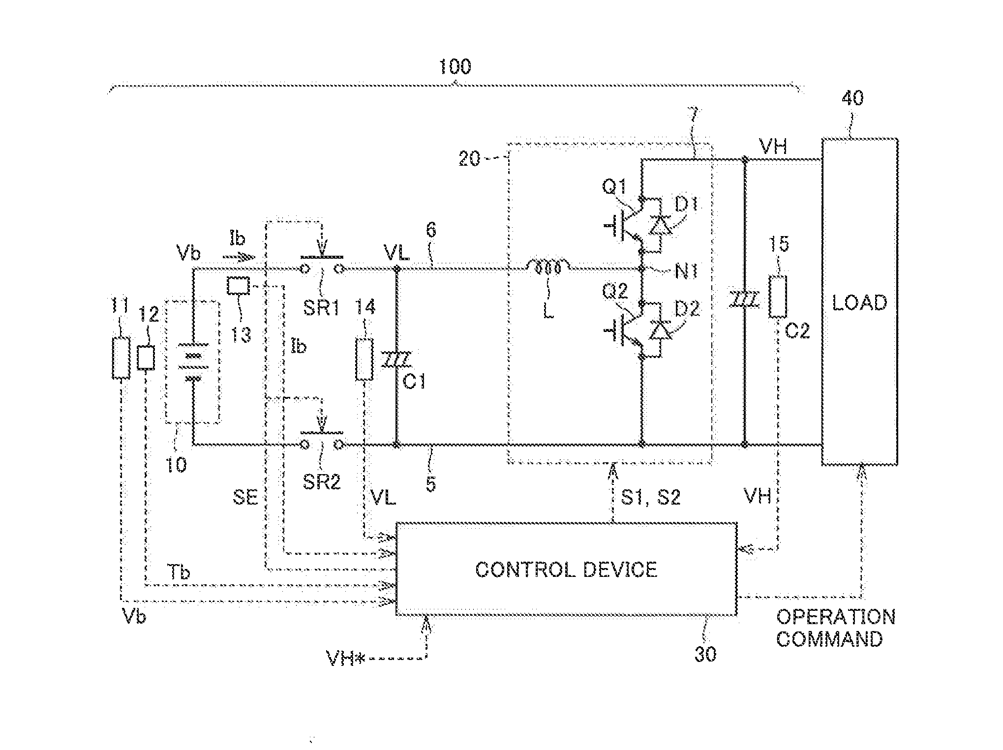
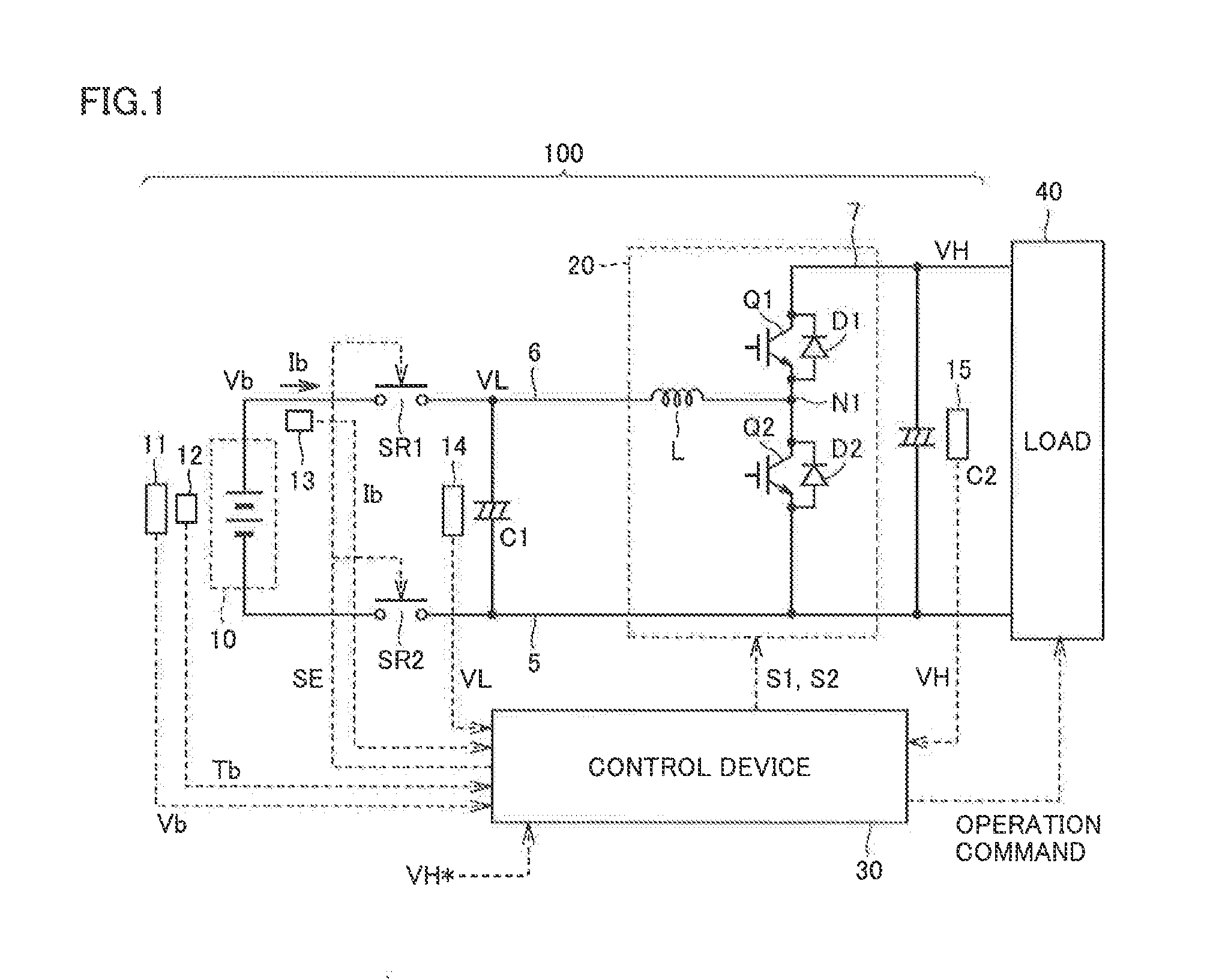
[0029]FIG. 1 is a block diagram illustrating the configuration of a power supply system according to the present embodiment.

[0030]Referring to FIG. 1, a power supply system 100 according to the embodiment of the present invention includes a power storage device 10, system relays SR1 and SR2, smoothing capacitors C1 and C2, a boost converter 20, and a control device 30.

[0031]Power storage device 10, which is a rechargeable DC power supply, is representatively configured of a battery such as a lithium-ion battery or a nickel-metal hydride battery. Alternatively, power storage device 10 can be configured also of an electric double layer capacitor or the like. In the following, power storage device 10 will be also referred to as a battery 10.

[0032]Battery 10 is provided with a voltage sensor 11 for detecting an output voltage Vb (battery voltage), a temperature sensor 12 for detecting a battery temperature Tb, and a current sensor 13 for detecting an output current Ib from battery 10.

[0...

second embodiment

[0122]In the second embodiment, an explanation will be given with regard to the control for further reliably limiting battery current Ib, that is, the passing current flowing through boost converter 20.

[0123]FIG. 10 is a block diagram illustrating the control for thermal protection of a boost converter according to the second embodiment.

[0124]When comparing FIG. 10 with FIG. 9, a Wout limitation unit 270 and an upper limit guard unit 280 are further provided for the control according to the second embodiment.

[0125]Wout limitation unit 270 sets discharge power upper limit value WoutD for thermal protection of boost converter 20 in accordance with current upper limit value IbmaxD set by current upper limit setting unit 200 and battery voltage Vb detected by voltage sensor 11. Specifically, the condition is set as WoutD=IbmaxD*Vb.

[0126]Upper limit guard unit 280 serves to guard base value WoutB that is set by discharge limitation unit 250 so as not to exceed WoutD that is set by Wout l...

third embodiment

[0130]In the third embodiment, the control for positively raising output voltage VH for thermal protection of boost converter 20 (diode D1) will be described.

[0131]FIG. 11 is a functional block diagram illustrating the control for thermal protection of a boost converter according to the third embodiment.

[0132]Referring to FIG. 11, the configuration according to the third embodiment is further provided with a lower limit voltage setting unit 305 and a voltage command value setting unit 310.

[0133]Lower limit voltage setting unit 305 sets VH lower limit voltage VHD from the aspect of thermal protection of boost converter 20 in accordance with cooling water temperature Tcw detected by temperature sensor 155 and battery current Ib detected by current sensor 13.

[0134]VH lower limit voltage VI-HD is set, for example, in accordance with the characteristics shown in FIG. 8. Specifically, in a region where Tc≦Tcw holds, VHD increases in accordance with cooling water temperature Tcw. Preferabl...


PUM


Abstract

A boost converter is configured of a boost chopper having a diode of an upper arm and a switching element of a lower arm. Output power from a battery to a load is limited such that a current flowing through boost converter does not exceed a current upper limit value for thermal protection of boost converter. The current upper limit value is set based not only on a cooling water temperature of boost converter but also on an output voltage VH of boost converter, in consideration of characteristics that, as output voltage VH rises, an amount of heat generated in diode decreases, diode being regarded as a main target of thermal protection since it receives a power running current to load. Thereby, the boost converter can be protected from overheating without excessively deteriorating vehicle traveling performance.

Description

[0001]This nonprovisional application is based on Japanese Patent Application No. 2014-244017 filed on Dec. 2, 2014, with the Japan Patent Office, the entire contents of which are hereby incorporated by reference.BACKGROUND OF THE INVENTION[0002]1. Field of the Invention[0003]The present invention relates to a power supply system, and more particularly to a power supply system applied to an electrically powered vehicle equipped with an electric motor for generating vehicle driving force and configured to include a boost converter for boosting a voltage from a power storage device.[0004]2. Description of the Background Art[0005]As a power supply system of an electrically powered vehicle such as an electric vehicle and a hybrid vehicle, for example, Japanese Patent Laying-Open No. 2011-87406 (PTD 1) discloses a configuration including a boost converter boosting a voltage from a power storage device and outputting the boosted voltage to a load.[0006]PTD 1 discloses that the maximum val...

Claims


Application Information

Patent Timeline
Patent Type & Authority Applications(United States)
IPC IPC(8): B60L11/18
CPCB60L11/1803B60L3/003B60L3/0046B60L3/0076H02M3/155H02P27/06B60L2240/54B60L50/15B60L58/12B60L58/26Y02T10/70Y02T10/7072B60L50/51
Inventor TAGUCHI, ETSUSHITAKAHASHI, AKIHIRO
Owner DENSO CORP
Why Eureka
Try Eureka