
Adapting electroforming techniques for the manufacture of architectural building elements

Inactive Publication Date: 2016-06-02
THE RGT OF THE UNIV OF MICHIGAN
View PDF6 Cites 0 Cited by
  • Summary
  • Abstract
  • Description
  • Claims
  • Application Information

AI Technical Summary

Benefits of technology

The patent text describes a method called electroforming that can be used to create outdoor and indoor architectural elements with minimal investment and customization capabilities. The process allows for variations in design and detailing that traditional metal forming techniques cannot achieve. The method can also be used with existing manufacturing infrastructure from other fields, making it more accessible for use in real-life applications. Overall, electroforming provides a cost-effective way to create highly customizable architectural elements.

Problems solved by technology

These techniques require large preliminary investment and infrastructure which ultimately leads to the production of standardized mass produced elements to compensate for early costs.
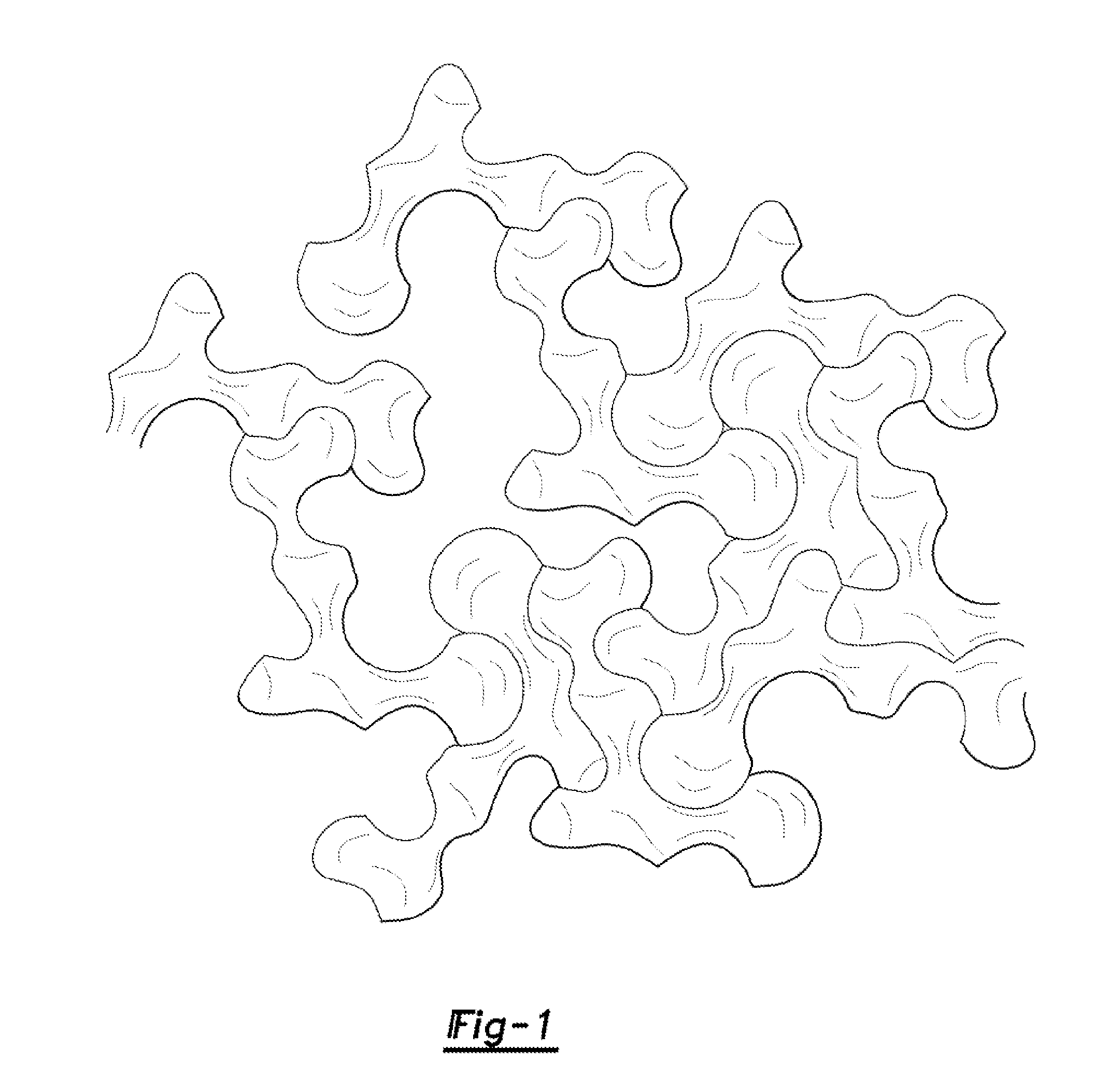
Additionally, electroforming can achieve formal variations impossible in standard metal forming techniques (undercutting, complex molds, embedded substrates, and refined detailing).

Method used


Image

  • Adapting electroforming techniques for the manufacture of architectural building elements
  • Adapting electroforming techniques for the manufacture of architectural building elements
  • Adapting electroforming techniques for the manufacture of architectural building elements

Examples


Embodiment Construction

[0023]Example embodiments will now be described more fully with reference to the accompanying drawings.

[0024]Example embodiments are provided so that this disclosure will be thorough, and will fully convey the scope to those who are skilled in the art. Numerous specific details are set forth such as examples of specific components, devices, and methods, to provide a thorough understanding of embodiments of the present disclosure. It will be apparent to those skilled in the art that specific details need not be employed, that example embodiments may be embodied in many different forms and that neither should be construed to limit the scope of the disclosure. In some example embodiments, well-known processes, well-known device structures, and well-known technologies are not described in detail.

[0025]The terminology used herein is for the purpose of describing particular example embodiments only and is not intended to be limiting. As used herein, the singular forms “a,”“an,” and “the” ...


PUM

PropertyMeasurementUnit
Thicknessaaaaaaaaaa
Shapeaaaaaaaaaa
Electrical conductoraaaaaaaaaa

Abstract

A method of manufacturing an architectural building element, including providing a mold or master having a surface that is conductive. The mold or master is suspended in an electrolyte solution. Electro-deposition of a material disposed in the electrolyte solution upon the mold or master is performed using electrical current. The mold or master is removed from the electrolyte solution upon electro-deposition of a predetermined thickness of a coating of the material on the mold or master. The coating is then divorced from the mold or master to form an architectural building element.

Description

CROSS-REFERENCE TO RELATED APPLICATIONS[0001]This application claims the benefit of U.S. Provisional Application No. 61 / 845,435, filed on Jul. 12, 2013. The entire disclosure of the above application is incorporated herein by reference.FIELD[0002]The present disclosure relates to the manufacture of architectural building elements and, more particularly, relates to adapting electroforming techniques for the manufacture of architectural building elements.BACKGROUND AND SUMMARY[0003]This section provides background information related to the present disclosure which is not necessarily prior art. This section also provides a general summary of the disclosure, and is not a comprehensive disclosure of its full scope or all of its features.[0004]Known techniques in the manufacture of metal stock materials used in the construction of static structures (i.e., buildings) are formed using common metalworking techniques on sheet or plate metal to create structural and ornamental elements. These...

Claims


Application Information

Patent Timeline
IPC IPC(8): C25D1/00C25D1/10C25D1/20
CPCC25D1/003C25D1/10C25D1/20C25D1/00
Inventor SIROTA, ANYABEAUCE, PATRICKFARGES, JEAN-LOUIS
Owner THE RGT OF THE UNIV OF MICHIGAN
Features
  • Generate Ideas
  • Intellectual Property
  • Life Sciences
  • Materials
  • Tech Scout
  • Unparalleled Data Quality
  • Higher Quality Content
  • 60% Fewer Hallucinations
Learn More