
Fan assembly for centrifugal blower and air conditioning apparatus including the same

Inactive Publication Date: 2016-06-02
SAMSUNG ELECTRONICS CO LTD
View PDF15 Cites 10 Cited by
  • Summary
  • Abstract
  • Description
  • Claims
  • Application Information

AI Technical Summary

Benefits of technology

The present invention is about a new fan assembly for a centrifugal blower that helps reduce power consumption and make the blower more efficient. It achieves this by using a blade that has multiple parts with different widths.

Problems solved by technology

The blade with this structure includes an area in which it is not necessary to discharge air, and thus a problem arises in that unnecessary power is consumed.
However, the blade is conceived to discharge a greater amount of air but does not consider consumption power.
Also, the present disclosure is not required to overcome the disadvantages described above, and an exemplary embodiment of the present disclosure may not overcome any of the problems described above.

Method used


Image

  • Fan assembly for centrifugal blower and air conditioning apparatus including the same
  • Fan assembly for centrifugal blower and air conditioning apparatus including the same
  • Fan assembly for centrifugal blower and air conditioning apparatus including the same

Examples


first embodiment

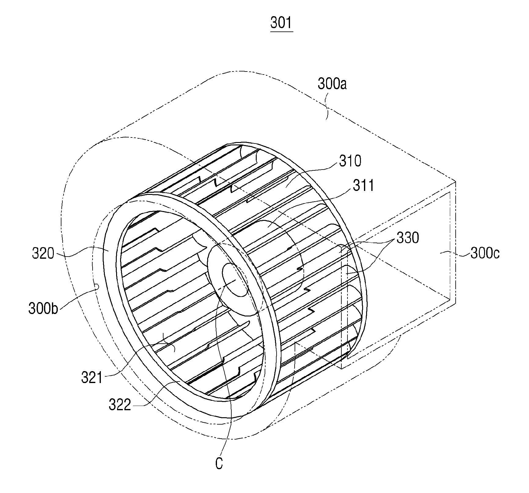
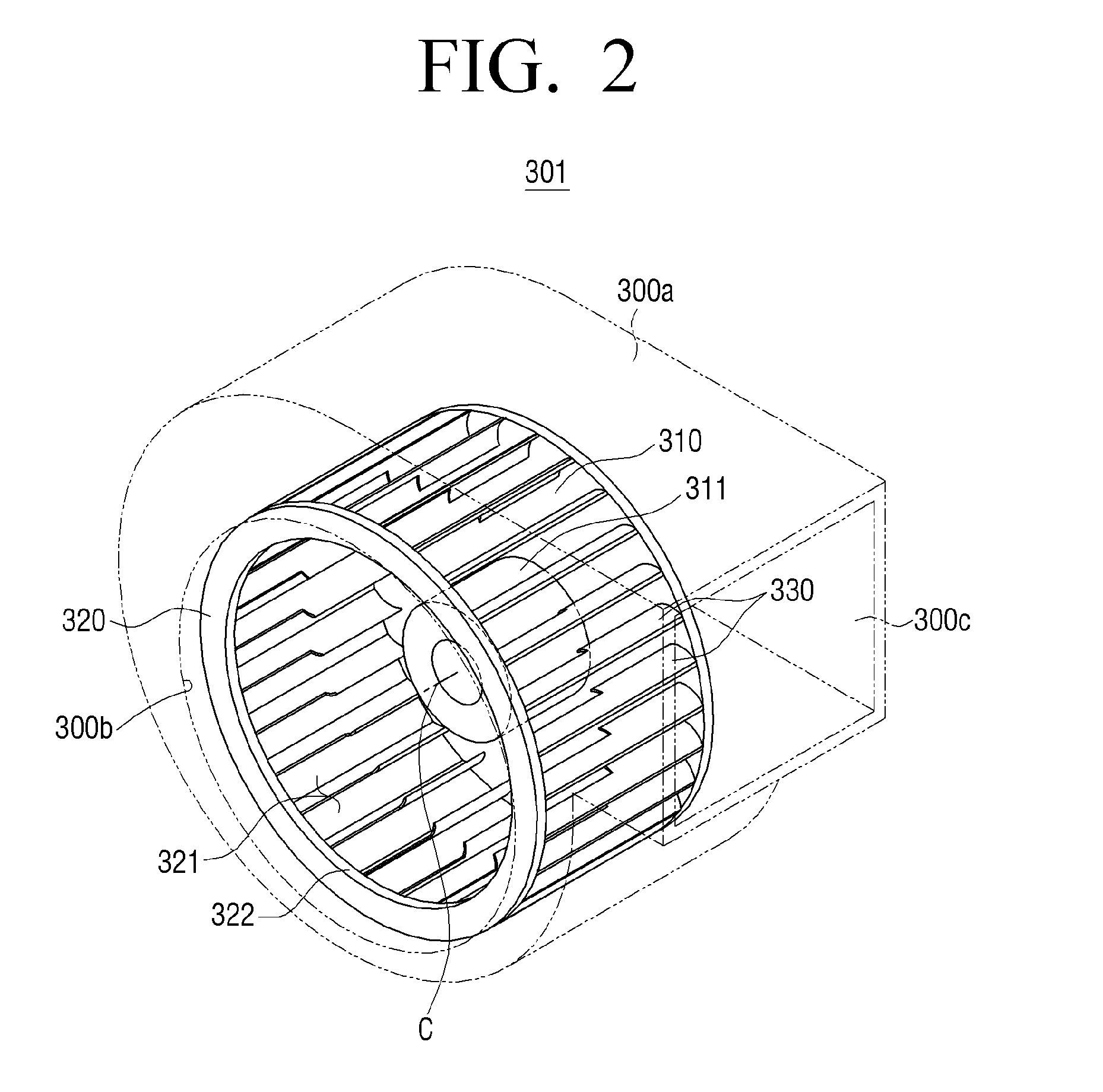
[0055]Referring to FIG. 3, a blade 330 according to the present disclosure is divided into a first portion 331 and a second portion 332 which have different widths according to the amount of air that is introduced through the inlet 321 and discharged in a radial direction of the fan assembly 301.

[0056]The first portion 331 is disposed adjacent to the inlet 321 and formed with a narrow and fixed or constant width W1 compared with a width W2 of the second portion 332, which in the embodiment also has a fixed or constant width W2.

[0057]In detail, in order to discharge the air introduced through the inlet 321, through the first portion 331 in the radial direction, a flow path of the air needs to be steeply changed to the radial direction immediately after the air passes through the inlet 321, and thus the amount of air discharged through the first portion 331 is smaller than the amount of air discharged through the second portion 332. Accordingly, the first portion 331 need not necessar...

second embodiment

[0067]Referring to FIG. 4, the blade 340 is formed in such a way that a portion 343 of an internally protruding portion of a second portion 342, adjacent to a first portion 341, is rounded. That is, the blade 340 is formed such that a width between the first portion 341 and the second portion 342 is not steeply changed, that is, the width is changed gradually.

[0068]Although not illustrated, a portion of an internally protruding portion of the first portion 341, adjacent to the second portion 342, may also be rounded.

[0069]Like in the first embodiment, the length of the first portion 341 is smaller than the length of the second portion 342.

[0070]When the blade 340 according to the second embodiment of the present disclosure is applied to the fan assembly 301, a flow direction of air introduced into the inlet 321 is changed towards the plurality of blades 340 with a predetermined curvature, like the blade 330 according to the first embodiment. In this case, as described above, the am...

third embodiment

[0072]With reference to FIG. 5, the blade 350 will be described.

[0073]The blade 350 according to the third embodiment is formed in such a way that the width of a first portion 351 is tapered towards the inlet 321. However, although the width of the first portion 351 is gradually tapered in FIG. 5, embodiments of the present disclosure are limited thereto, and the width of the first portion 351 may be non-gradually tapered. In addition, the first portion 351 may have a constant width, but a second portion 352 may have a width that is gradually or non-gradually tapered towards the inlet 321.

[0074]In addition, like the aforementioned blade 330 according to the first embodiment, the length of the first portion 351 may be smaller than the length of the second portion 352.

[0075]When the blade 350 according to the third embodiment is applied to the fan assembly 301, a flow direction of air introduced to the inlet 321 is changed towards the plurality of blades 350 with a predetermined curv...


PUM


Abstract

A fan assembly for a centrifugal blower and an air conditioning apparatus including the same are provided. The fan assembly for the centrifugal blower includes a first support configured to receive a driving force from a driving source to rotate, a plurality of blades having one end supported by the first support and arranged with an interval in a circumferential direction of the first support, and a second support configured to support the other end of the plurality of blades and including an air inlet formed therein, wherein the plurality of blades include a first portion disposed adjacent to the air inlet, and a second portion further from the air inlet than the first portion and having a wider width than the first portion, and at least one of the first and second portions has a constant width.

Description

CROSS-REFERENCE TO RELATED APPLICATIONS[0001]This application claims priority from Korean Patent Application No.10-2014-0167420, filed on Nov. 27, 2014, in the Korean Intellectual Property Office, the disclosure of which is incorporated herein by reference in its entirety.BACKGROUND[0002]1. Field[0003]Apparatuses and methods consistent with the present disclosure relate to a fan assembly for a centrifugal blower and an air conditioning apparatus including the same, and more particularly, to a fan assembly for a centrifugal blower, for reducing consumption power, and an air conditioning apparatus including the same.[0004]2. Description of the Related Art[0005]In general, a fan for a centrifugal blower introduces air in a rotation axis direction, discharges air in a radial direction, and has a greater flow rate than other fans with the same size and rotational speed. In other words, since the fan for the centrifugal blower may have a lower external circumference or rotational speed th...

Claims


Application Information

Patent Timeline
IPC IPC(8): F04D17/10F04D29/42
CPCF04D29/4226F04D17/10B60H1/00471F04D17/16F04D29/283F04D29/30F24F1/0022F05D2240/303F04D29/305F24F1/00
Inventor JANG, KEUN-JEONGKIM, BYUNG-GHUNSEO, YONG-HOKWON, HYUNG-JINKIM, YOUNG-JAESEO, HYEONG-JOON
Owner SAMSUNG ELECTRONICS CO LTD
Learn More