Silty floating mud collection device

a floating mud collection and floating technology, applied in the field of soil samplers, can solve the problems that foregoing soil samplers cannot be applied to collect floating mud in a flowing state in different depths, can not be applied to collect floating mud in different depths, and affect the quality of samples, etc., and achieves low cost and easy disassembly

Active Publication Date: 2016-06-02
CCCC THIRD HARBOR CONSULTANTS
View PDF4 Cites 87 Cited by
  • Summary
  • Abstract
  • Description
  • Claims
  • Application Information

AI Technical Summary

Benefits of technology

[0022]Compared with the prior art, the present invention has the following beneficial effects:
[0023](1) After the collection device reaches a specified depth, a drill rod applies pressure, so that the drive cylinder drives the lug cover plate and the turning cover to close the upper-end opening and the lower-end opening of the sampler barrel respectively, and therefore a mud sample can be kept in an undisturbed state well and is free from the influence of the environment, water depth, and the like, and a sampling rate is improved.
[0025](3) The entire collection device uses modular design and a standard structure, the costs are low, and disassembly is easy because parts are tightly connected through thread.

Problems solved by technology

However, they are applied to stratum such as soft clay, sand gravel, and differentiated rock; because the floating mud layer involved in the nautical depth has an excessively high water content, so that the floating mud is in a flowing state.
Obviously, the foregoing soil samplers cannot be applied to collect floating mud in a flowing state in different depths.
In addition, the foregoing soil samplers use a direct pressing, hammer pressing or pressure rotating sampling manner, which cannot be applied to collect the floating mud either.
Because some sampling devices are of an opening manner, quality of samples will be affected by a lifting process, and deeper water indicates a larger impact.
Although all the foregoing three soil samplers may be applied to collecting underwater silty floating mud, but there are limitations.
The second and the third soil samplers have the following problems: There are relatively large differences existing in water content, specific gravity, density, sand grain content of floating, flowing and silty mud, and soft or plastic soil, which form different friction; friction of floating and flowing mud is the smallest, and a high sampling rate cannot be achieved while a closing piece of the soil sampler is closed by control of friction.
In addition, a lower-part structure of the first soil sampler uses vacuum negative pressure sampling, which is universally used in current survey technologies and is applicable to sampling of soft or plastic soil with a shape; the second and the third soil samplers use a closing device, which is an improvement for successively collecting floating mud, but the closing device is formed by backstop (closing) pieces, factors such as synchronous closing of the closing pieces and space between closing pieces all cause leaking of water in floating mud with high water content, and therefore affect accuracy of sample data.
Moreover, a sample upper opening cover during sample collecting is not considered in the prior art, and undisturbed state of the entire sample cannot be ensured.

Method used


Image

  • Silty floating mud collection device
  • Silty floating mud collection device
  • Silty floating mud collection device

Examples


Embodiment Construction

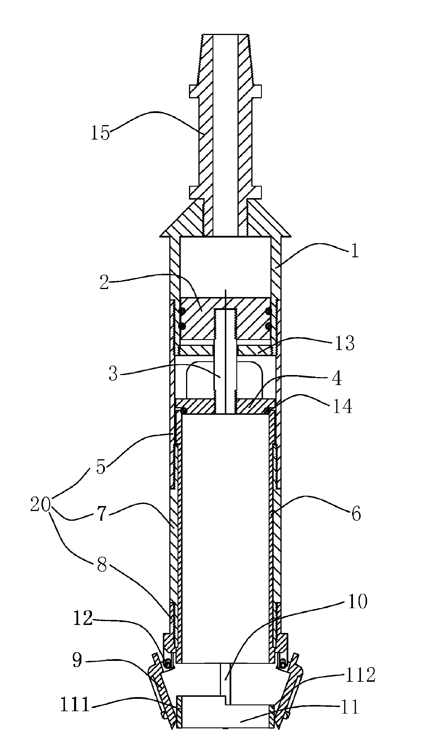
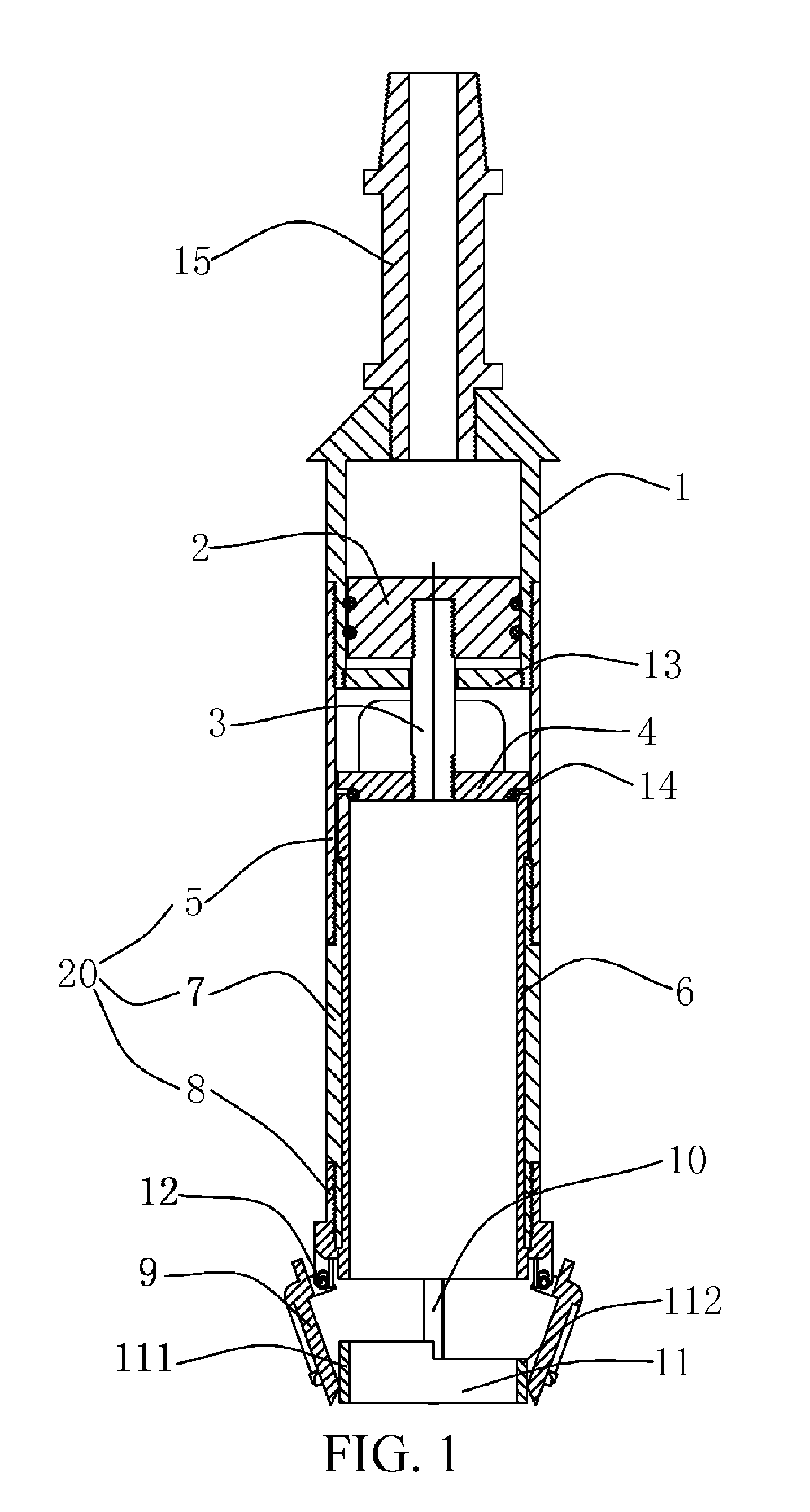
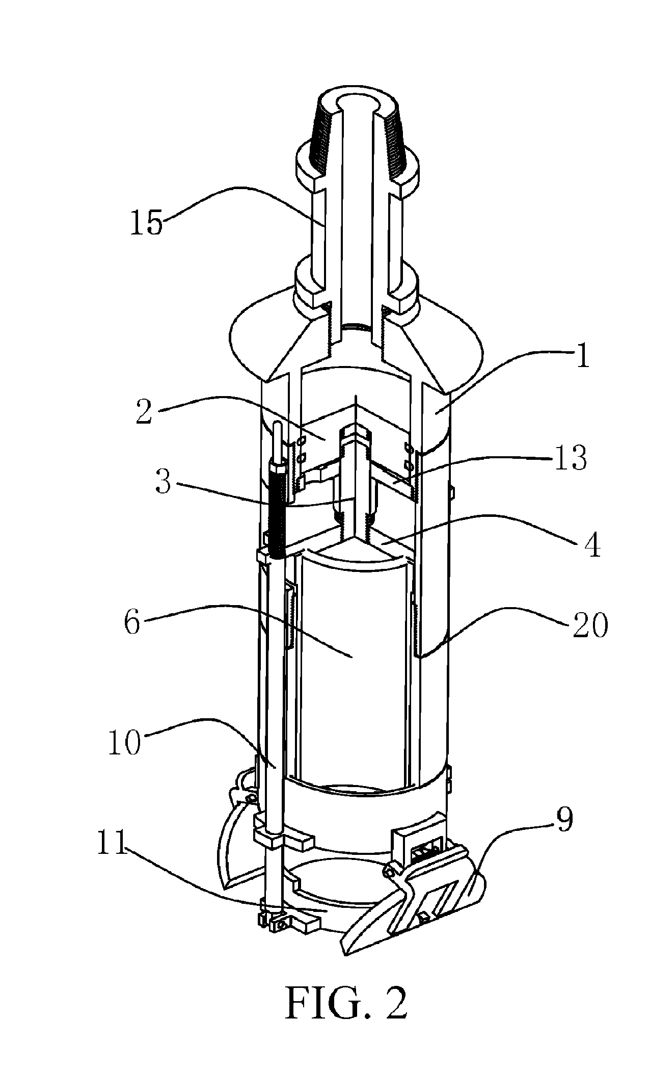
[0036]The present invention is further explained in detail with reference to the accompanying drawings and specific embodiments, and a person skilled in the art may understand other advantages and effects of the present invention more clearly.

[0037]It should be noted that, structures, ratios, and sizes drawn in the accompanying drawings of the specification are merely used to cooperate with the specific embodiments, to help a person skilled in the art to know conceptions of the present invention more clearly, but are not intended to limit the protection scope of the present invention. Any structure modification, ratio relationship change, or size adjustment without affecting implementation of effects and objectives of the present invention should fall within the protection scope of the present invention. For easy understanding, “upper”, “lower”, “left”, and “right” in the following descriptions are all described according to a layout direction of the accompanying drawings of the spe...


PUM

PropertyMeasurementUnit
rheologicalaaaaaaaaaa
thicknessaaaaaaaaaa
densityaaaaaaaaaa

Abstract

A silty floating mud collection device, which includes a drive cylinder, an outer sleeve, a sampler barrel, an lug cover plate, a turning cover, a control ring and a control rod, where the drive cylinder includes a cylinder liner, a piston and a piston rod; the outer sleeve is fixedly connected below the cylinder liner; the sampler barrel is detachably installed inside the outer sleeve; the lug cover plate is fixedly connected to a lower end of the piston rod, and can close an upper-end opening of the sampler barrel; the turning cover is turnably installed at a lower end of the outer sleeve, and can close a lower-end opening of the sampler barrel; the control ring is located below the sampler barrel, and is used to block the turning cover which is in an open state; and an upper end of the control rod is connected to the lug cover plate, and a lower end of the control rod is connected to the control ring.

Description

BACKGROUND OF PRESENT INVENTION[0001]1. Field Of Invention[0002]The present invention relates to a silty floating mud collection device of coastal engineering, and more specifically belongs to the field of sampling and testing technologies.[0003]2. Description of Related Arts[0004]Exploitation of nautical depth resources is: navigating by using a floating mud layer below a current water depth in a silty port area waterway and a coastal waterway having a silt property, which not only can increase a navigable depth, but also can reduce maintenance costs for the navigable depth, prolong a maintenance dredging period for ports, waterways and berths, and improve port economic benefits. Since the 80s of the 20th century, China began to develop and apply the nautical depth at some ports, and released a Ministry of Communications industry standard “Silty Seaport Nautical Depth Application Technology Specification” (JTJ / T325-2006), which is then enforced as a formal standard in China. To det...

Claims


Application Information

Patent Timeline
Patent Type & Authority Applications(United States)
IPC IPC(8): G01N1/10
CPCG01N2001/1025G01N1/10E21B25/10E21B25/14E21B49/025G01N2001/085
Inventor NIU, JIANDINGHU, JIANPINGCHEN, ZHIYONGCHENG, ZEKUNCHENG, LIMINLI, XIAOJIEDONG, JIAOSHEWANG, NIANXIWANG, ZHAOMING
Owner CCCC THIRD HARBOR CONSULTANTS
Why Eureka
Try Eureka