Siginal generator and calibrating method thereof

a generator and siginal technology, applied in the field ofsignal generators, can solve the problems of reducing the performance of the signal generator, affecting the clock frequency, and affecting and achieving the effect of reducing the frequency of the output oscillation signal

Active Publication Date: 2016-06-02
MEDIATEK INC
View PDF2 Cites 1 Cited by
  • Summary
  • Abstract
  • Description
  • Claims
  • Application Information

AI Technical Summary

Benefits of technology

[0007]In some embodiments, the power mesh has a resistance, and the frequency of the output oscillation signal is decreased because of the resistance of the power mesh.

Problems solved by technology

As a matter of fact, the clock frequency is often negatively affected by a normal IR-drop in the circuit.
The so-called IR-drop represents that the supply voltage of the signal generator is decreased because of imperfect conductor lines, and the IR-drop results in a lower supply voltage and a lower clock frequency, which degrade the performance of the signal generator.

Method used


Image

  • Siginal generator and calibrating method thereof
  • Siginal generator and calibrating method thereof
  • Siginal generator and calibrating method thereof

Examples


Embodiment Construction

[0026]In order to illustrate the purposes, features and advantages of the invention, the embodiments and figures of the invention will be described in detail as follows.

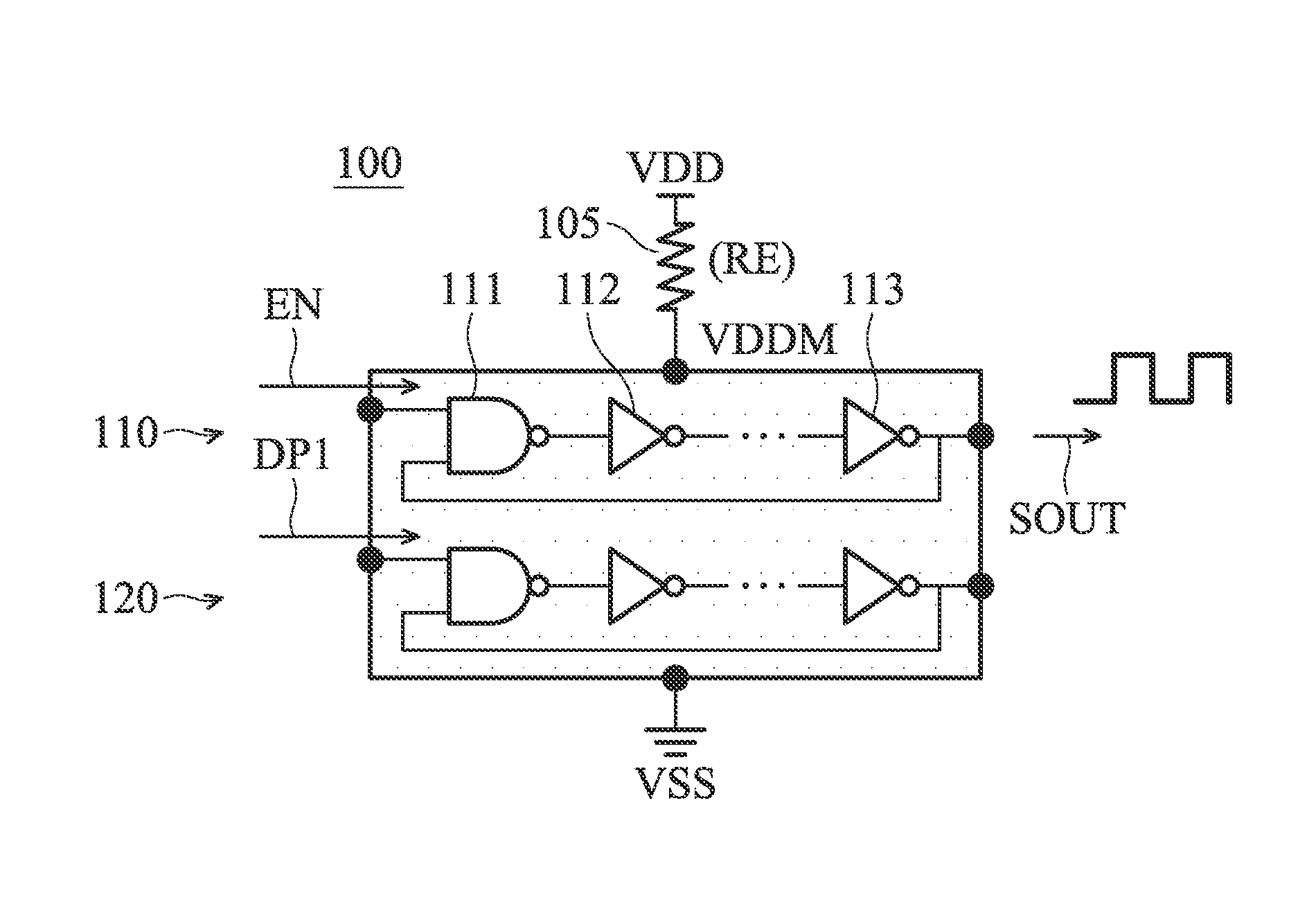
[0027]FIG. 1 is a diagram of a signal generator 100 according to an embodiment of the invention. The signal generator 100 may be a clock generator for use in digital circuits. As shown in FIG. 1, the signal generator 100 includes a main ring oscillator 110 and a first ring oscillator 120. The main ring oscillator 110 is supplied by a power voltage VDD, and is configured to generate an output oscillation signal SOUT for driving a variety of circuit elements. The output oscillation signal SOUT may be a clock signal, such as a square wave or a triangular wave. The main ring oscillator 110 is coupled through a power mesh 105 to the power voltage VDD. More specifically, the main ring oscillator 110 may include a plurality of oscillation elements, such as inverters, NAND gates, and / or NOR gates. The power mesh 105 may incl...


PUM


Abstract

A signal generator includes a main ring oscillator and a first ring oscillator. The main ring oscillator is supplied by a power voltage, and is configured to generate an output oscillation signal. The main ring oscillator is coupled through a power mesh to the power voltage. The first ring oscillator is supplied by the power voltage. The first ring oscillator is similar or identical to the main ring oscillator. The first ring oscillator is coupled through the power mesh to the power voltage. The first ring oscillator is used to calibrate a frequency of the output oscillation signal.

Description

CROSS REFERENCE TO RELATED APPLICATIONS[0001]This application claims the benefit of U.S. Provisional Application No. 62 / 085,357, filed on Nov. 28, 2014, the entirety of which is incorporated by reference herein.BACKGROUND OF THE INVENTION[0002]1. Field of the Invention[0003]The disclosure generally relates to a signal generator, and more specifically, to a signal generator with a function of frequency calibration.[0004]2. Description of the Related Art[0005]Signal generators are commonly used in the field of digital circuits. For example, a signal generator may be configured to generate a clock signal for driving a variety of circuit elements, and its clock frequency should be very accurate. As a matter of fact, the clock frequency is often negatively affected by a normal IR-drop in the circuit. The so-called IR-drop represents that the supply voltage of the signal generator is decreased because of imperfect conductor lines, and the IR-drop results in a lower supply voltage and a lo...

Claims


Application Information

Patent Timeline
Patent Type & Authority Applications(United States)
IPC IPC(8): H03L7/00H03K3/03
CPCH03L7/00H03K3/0315H03K3/011
Inventor CHEN, YI-FENGTSAI, TSUNG-YINGLIU, HENG-MENGHSUEH, SUNG-YUN
Owner MEDIATEK INC
Why Eureka
Try Eureka