Novel millimeter wave sub-sampling DDS frequency mixing fractional frequency division phase-locked loop structure

A fractional frequency division, phase-locked loop technology, applied in the direction of electrical components, automatic power control, etc., can solve the problems of high DDS output frequency, phase error, high power consumption, etc., to achieve good filtering effect, reduce power consumption, good The effect of linearity

Active Publication Date: 2020-12-11
XIDIAN UNIV
View PDF9 Cites 0 Cited by
  • Summary
  • Abstract
  • Description
  • Claims
  • Application Information

AI Technical Summary

Problems solved by technology

The TDC structure uses the effect of phase accumulation, so that the sampling clock can achieve phase accumulation and achieve the effect of decimal sampling, but the minimum resolution accuracy of this structure is affected by the process, and phase errors are easily introduced during the phase accumulation process.
The Delta-sigma structure uses the frequency divider to generate outputs with different integer frequency division ratios within a certain period to achieve the effect of the average output being a fractional frequency division. The output frequency linearity of this scheme is not good and the frequency accuracy is low.
The traditional mixer solution performs mixing at the output of the VCO, which requires a very high output frequency of the DDS and consumes a lot of power

Method used


Image

  • Novel millimeter wave sub-sampling DDS frequency mixing fractional frequency division phase-locked loop structure
  • Novel millimeter wave sub-sampling DDS frequency mixing fractional frequency division phase-locked loop structure
  • Novel millimeter wave sub-sampling DDS frequency mixing fractional frequency division phase-locked loop structure

Examples


Embodiment 1

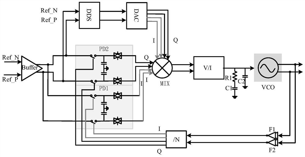
[0041] See figure 2 , figure 2 It is a schematic circuit structure diagram of a novel millimeter-wave sub-sampling DDS mixing fractional frequency division phase-locked loop structure provided by an embodiment of the present invention. This embodiment provides a novel millimeter-wave sub-sampling DDS fractional frequency-division phase-locked loop structure. The phase-locked loop structure includes: Phase PD2, DDS (direct digital frequency synthesizer), DAC (digital-to-analog converter), multiplier (ie MIX), voltage-current conversion circuit (ie V / I), low-pass filter, first inverter chain F1, second inverter chain F2, frequency divider (ie / N) and voltage controlled oscillator (ie VCO), where,

[0042] The first output end and the second output end of the buffer are respectively connected to the first input end and the second input end of the DDS, and the first output end and the second output end of the buffer are respectively connected to the first sub-sampling phase de...


PUM


Abstract

The invention discloses a novel millimeter wave sub-sampling DDS frequency mixing fractional frequency division phase-locked loop structure. The structure comprises a buffer, a first sub-sampling phase discriminator PD1, a second sub-sampling phase discriminator PD2, a DDS, a DAC, a multiplier, a voltage and current conversion circuit, a low-pass filter, a first inverter chain F1, a second inverter chain F2, a frequency divider and a voltage-controlled oscillator. Frequency mixing is carried out after sampling output, the required DDS output frequency is greatly reduced, and good linearity andlow power consumption can be achieved while the power consumption is reduced. The structure has the characteristics that the high-resolution characteristic of the DDS output signal frequency is not influenced by a phase-locked loop, the phase-locked loop enables a frequency synthesizer to jump in a wide frequency range in a minimum frequency stepping manner, and the DDS provides the capability ofjumping in a narrow frequency range in a very small frequency stepping manner. Therefore, the broadband frequency conversion speed depends on the loop locking time of the phase-locked loop, and the narrowband frequency conversion speed after loop locking depends on the frequency conversion time of the DDS.

Description

technical field [0001] The invention belongs to the technical field of analog-digital hybrid integrated circuits, and in particular relates to a novel millimeter-wave sub-sampling DDS frequency mixing fractional frequency division phase-locked loop structure. Background technique [0002] A phase locked loop (PLL, Phase Locked Loop) is a phase locked feedback loop, which is a typical feedback control circuit. It uses an externally input reference signal to control the frequency and phase of the internal oscillation signal of the loop. Realize automatic tracking of output signal frequency to input signal frequency, generally used in closed-loop tracking circuit. With the development of 5G, the industry has higher and higher requirements for the frequency and phase noise of the phase-locked loop. Poor spurious and phase noise can cause spectral aliasing of adjacent channel signals, reducing the signal-to-noise ratio. The spurs in the traditional phase-frequency and phase-de...

Claims


Application Information

Patent Timeline
Patent Type & Authority Applications(China)
IPC IPC(8): H03L7/18H03L7/087H03L7/099H03L7/08
CPCH03L7/18H03L7/087H03L7/0992H03L7/0802Y02D30/70
Inventor 刘马良肖金海朱樟明杨银堂
Owner XIDIAN UNIV
Why Eureka
Try Eureka