Stripping vessel for removing hydrocarbons entrained in catalyst particles

a technology of hydrocarbons and stripping vessels, which is applied in the field of stripping vessels, can solve the problems of large distance between the structure packing and the inlet to the stripping section, large surface area of catalyst particles employed in fcc processes, and large amount of hydrocarbons being withdrawn from the reaction zone with the catalyst, so as to reduce the impact of catalyst flow, reduce the impact of catalyst compression and mal-distribution, and reduce the effect of catalyst over accumulation

Active Publication Date: 2016-06-09
UOP LLC
View PDF0 Cites 11 Cited by
  • Summary
  • Abstract
  • Description
  • Claims
  • Application Information

AI Technical Summary

Benefits of technology

[0012]It has been discovered that by utilizing a grid in a space above a structured packing section, the over accumulation of catalyst within the stripping vessel can be minimized. The number of grids required is preferably determined by a maximum spacing between grids before over accumulation and gas bypassing occurs With such a grid and / or the preferred spacing above the structured packing, the catalyst compression and mal-distribution in the stripping vessel can be minimized without requiring a large amount of additional equipment and without negatively impacting the flow of catalyst and vapor.
[0013]Therefore in a first aspect of the present invention, the invention may be generally characterized as providing a stripping vessel for removing hydrocarbons from catalyst. Broadly, the stripping vessel comprises an inlet configured to receive a stream of spent catalyst particles, a first stripping section, a second stripping section, and an outlet. At least some of the spent catalyst particles comprise entrained hydrocarbons. The first stripping section includes at least one grid, and each grid includes at least one opening to allow catalyst to pass there though. The second stripping section includes a structured packing comprised of a plurality of ribbons. The at least one grid in the first stripping section is spaced from the structured packing of the second stripping section so as to minimize an accumulation of catalyst on top of stripping sections. The outlet is configured to pass catalyst particles from the stripping vessel.

Problems solved by technology

However, the catalyst particles employed in FCC processes typically have a large surface area, which is due to a great multitude of pores located in the particles.
Although the quantity of hydrocarbons retained on each individual catalyst particle may be very small, the vast amount of catalyst and the high catalyst circulation rate which is typically used in modern FCC processes results in a significant quantity of hydrocarbons being withdrawn from the reaction zone with the catalyst.
In existing FCC stripping vessels which have been reconfigured to include structured packing, since the structured packing may occupy less vertical space within the vessel, there may be a large distance between the structure packing and the inlet to the stripping section.
If this space is left devoid of equipment, the catalyst may accumulate which requires a refiner to maintain a higher catalyst inventory.
Additionally, the over accumulation of catalyst can result in catalyst compression leading to gas bypassing where the rising steam will channel through the stripping vessel without entering into an emulsion phase with the catalyst to remove the entrained hydrocarbons.
This leads to a reduction in stripping efficiency and hydraulic issues in, for example, the reactor, the stripping vessel, and the spent catalyst standpipe.

Method used


Image

  • Stripping vessel for removing hydrocarbons entrained in catalyst particles
  • Stripping vessel for removing hydrocarbons entrained in catalyst particles
  • Stripping vessel for removing hydrocarbons entrained in catalyst particles

Examples


Embodiment Construction

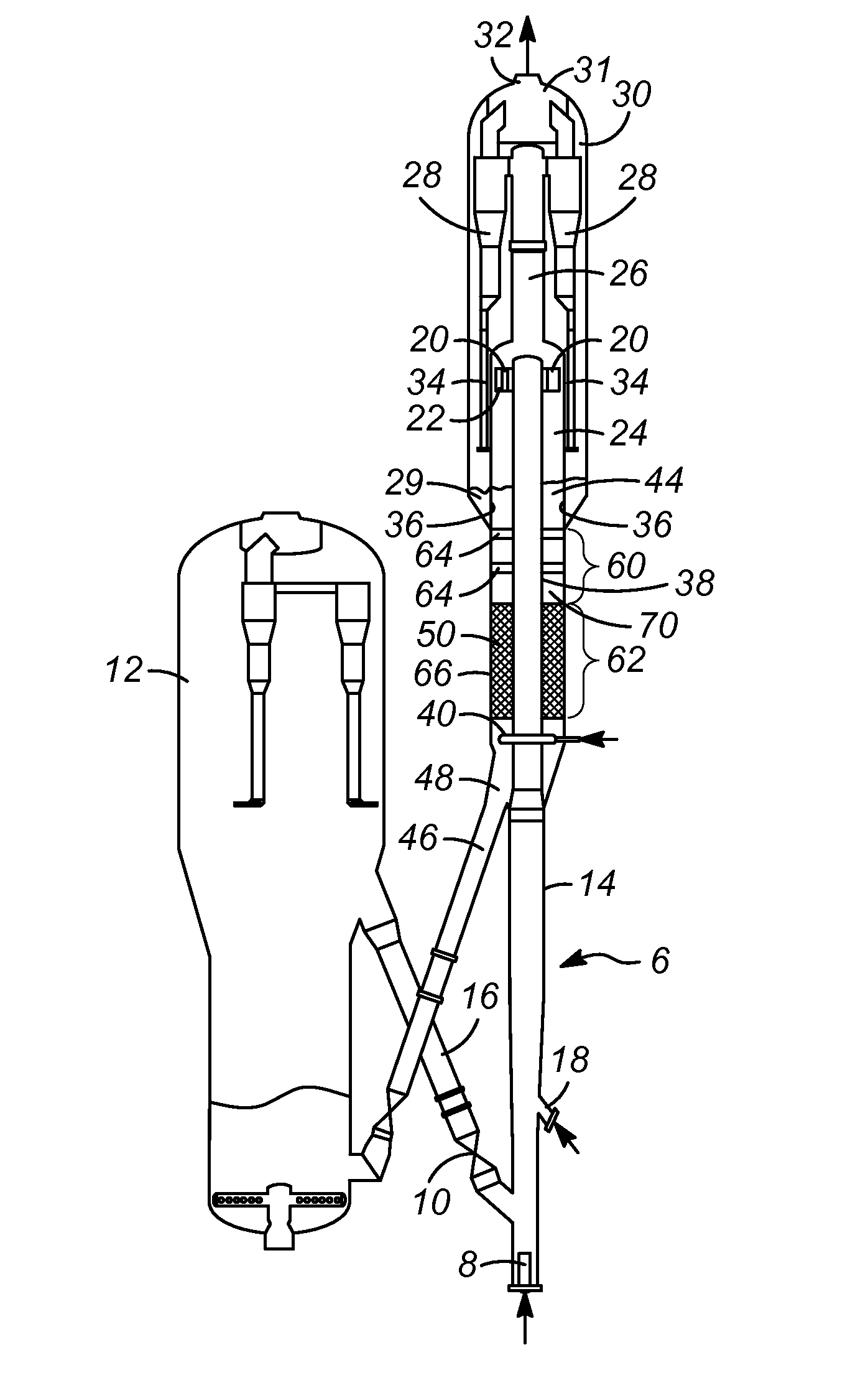
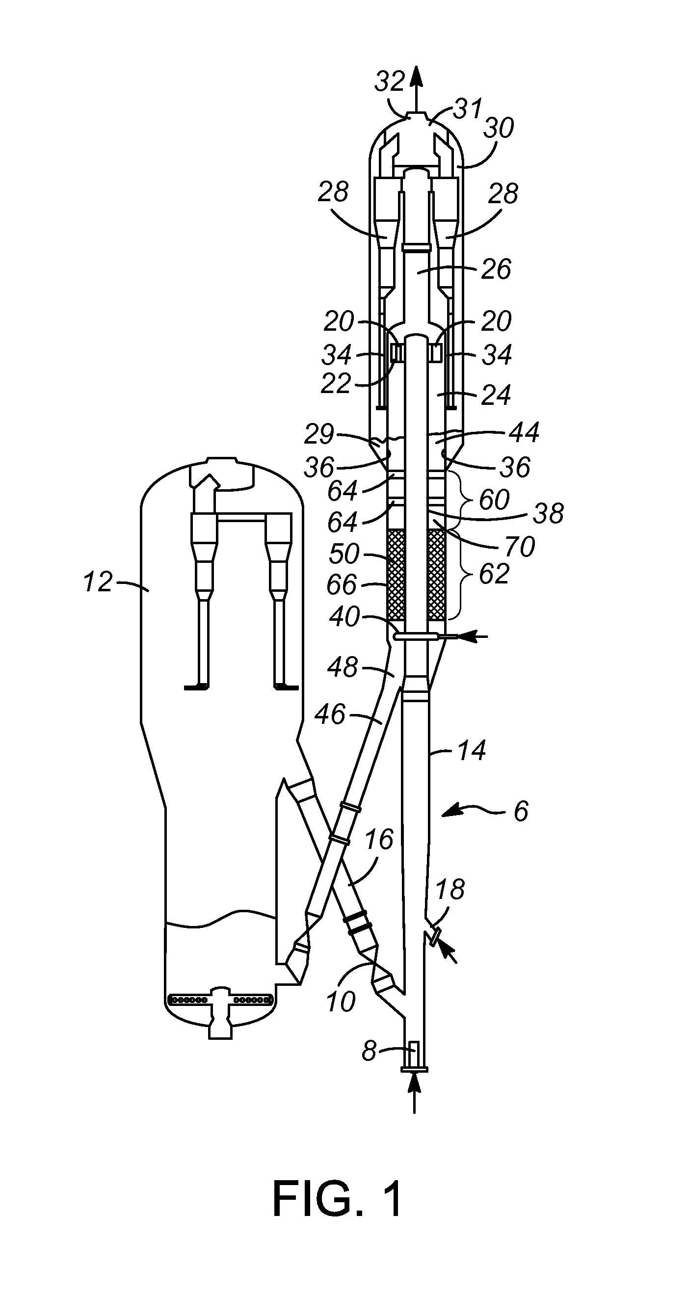
[0033]As discussed above, a design for a stripping vessel has been developed in which a grid or grids are disposed apart from a section of structure packing. The grid(s) will distribute catalyst that flows downward through the vessel, countercurrent to a stripping medium. The grids(s) will occupy the empty space above the inlet of the vessel to avoid over accumulation of the catalyst. It is contemplated that such a design is especially applicable to an FCC process and FCC process unit that is being retrofitted to include newer and more efficient stripping sections. The grids will occupy the empty space above or below the stripping section with structure packing and minimize the over accumulation of the catalyst.

[0034]With reference to the attached drawings, one or more embodiments of the present invention will now be described with the understanding that these embodiments are merely exemplary of the aspects and principles of the present invention.

[0035]The present invention comprise...


PUM

PropertyMeasurementUnit
distanceaaaaaaaaaa
distanceaaaaaaaaaa
distanceaaaaaaaaaa

Abstract

A stripping vessel for removing hydrocarbons from a catalyst and a process for removing hydrocarbons from a catalyst. In an FCC unit, the stripping vessel includes first and second stripping sections. The first stripping section includes at least one grid having a plurality of interesting members and openings therebetween. The second stripping section includes structured packing such as a plurality of ribbons. The one or more grids are spaced from the structured packing, and from each other, so as to minimize the accumulation of catalyst within the stripping vessel, preferably between about 0.91 m (3 ft) to about 1.5 m (5 ft).

Description

FIELD OF THE INVENTION[0001]This invention relates generally to a vessel used to recover hydrocarbons from a catalyst, and more particularly to a vessel use to recover hydrocarbons entrained in a catalyst and a process for recovering same.BACKGROUND OF THE INVENTION[0002]A variety of processes contact finely divided particulate material with a hydrocarbon containing feed under conditions wherein a fluid maintains the particles in a fluidized condition to effect transport of the solid particles to different stages of the process. Fluid catalytic cracking (FCC) is a prime example of such a process that contacts hydrocarbons in a reaction zone with a catalyst composed of finely divided particulate material. The hydrocarbon feed fluidizes the catalyst and typically transports it in a riser as the catalyst promotes the cracking reaction. As the cracking reaction proceeds, substantial amounts of hydrocarbon, called coke, are deposited on the catalyst.[0003]A high temperature regeneration,...

Claims


Application Information

Patent Timeline
Patent Type & Authority Applications(United States)
IPC IPC(8): B01J38/06B01J8/34
CPCB01J38/06B01J2208/00761B01J2208/00752B01J8/34B01J8/26B01J2219/3221B01J2219/32241B01J29/90
Inventor PALMAS, PAOLOCRAIG, ANDREW JONATHAN
Owner UOP LLC
Why Eureka
Try Eureka