Thermal Cutting Machine

a cutting machine and cutting edge technology, applied in the direction of soldering equipment, manufacturing tools, auxillary welding devices, etc., can solve the problems of adversely affecting the work environment, fire hazards in the factory, etc., and achieve the effects of reducing the damage to the tip portion of the torch, avoiding defective cutting caused by spatter dropping onto the workpiece surface, and reducing the accumulation of spatter on certain areas of the covering member

Inactive Publication Date: 2009-02-19
KOMATSU IND CORP
View PDF3 Cites 17 Cited by
  • Summary
  • Abstract
  • Description
  • Claims
  • Application Information

AI Technical Summary

Benefits of technology

[0024]According to the first or fifth aspect of the invention, flying of spatter can be confined within a narrow area by use of a covering member that covers at least a specified angular range of the outer periphery of the torch. In addition, the covering member is provided with an opening portion to allow a flow of air from the nozzle of the torch to the opening portion. The provision of the opening portion enables a part of spatter to escape to the outside of the covering member through the opening portion after hitting against the covering member and losing its momentum, so that the accumulation of spatter on particular areas of the covering member can be minimized. As a result, occurrence of defective cutting caused by the spatter dropping onto the workpiece surface can be avoided and damage to the tip portion of the torch can be extremely reduced. Additionally, the need to frequently clean the inside of the covering member can be eliminated.
[0025]By employing the arrangement of the seventh aspect, the spatter flying radially from the torch is allowed to hit against the shielding plates and change its course without fail, whereby the spatter can be steadily cooled.
[0026]According to the arrangement of the eighth aspect, the spatter, which has hit against the shielding plates, can change its course without going back inwardly from the shielding plates so that the accumulation of the spatter on the shielding plates can be more reliably prevented.
[0027]According to the arrangement of the ninth aspect, the spatter can change its course to a non-diffusive direction after hitting against the shielding plates, so that a more reliable spatter flying inhibiting effect and spatter accumulation inhibiting effect can be ensured.

Problems solved by technology

This not only adversely affects the work environment but also could cause fire hazard in the factory.

Method used


Image

  • Thermal Cutting Machine
  • Thermal Cutting Machine
  • Thermal Cutting Machine

Examples


Embodiment Construction

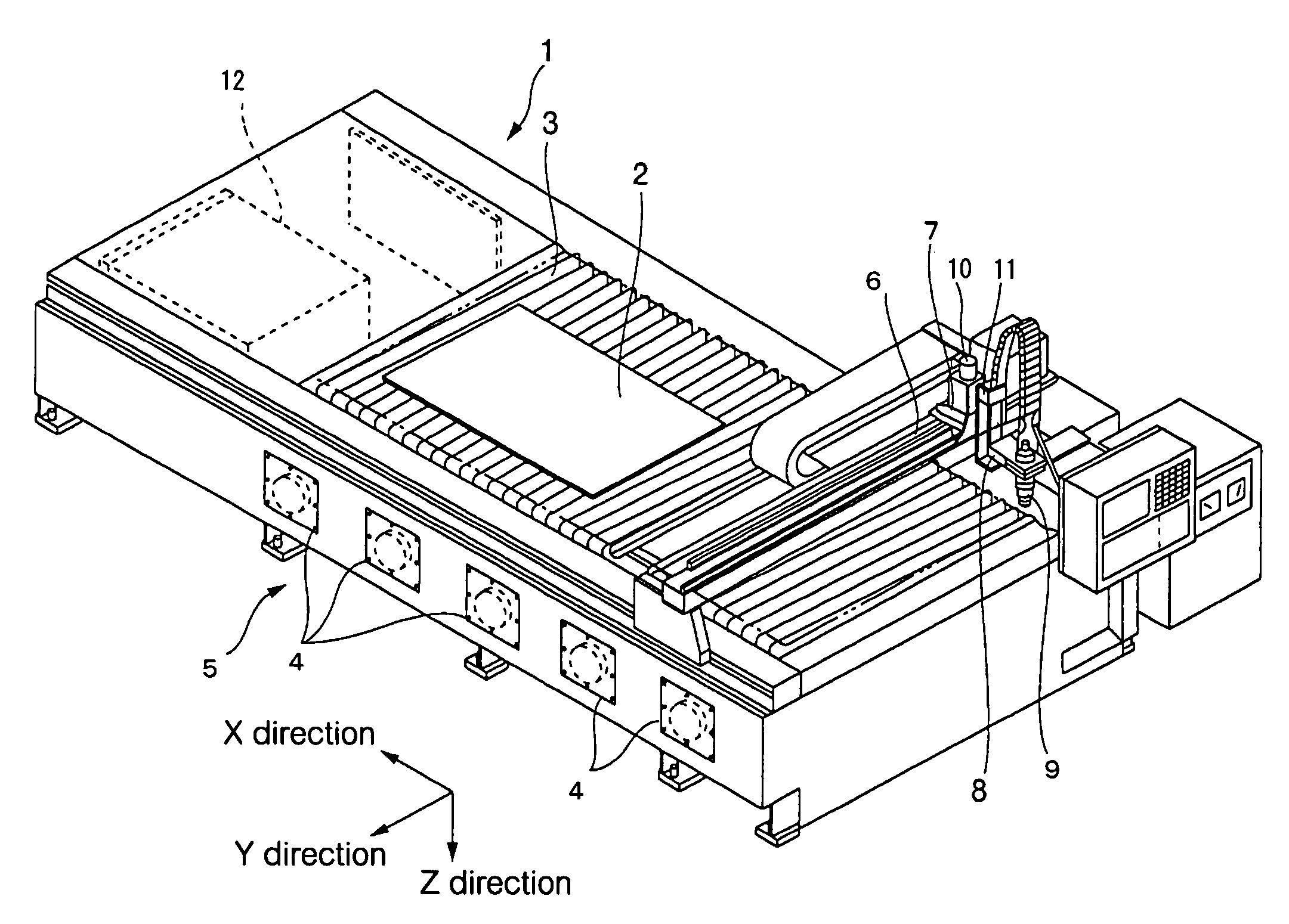
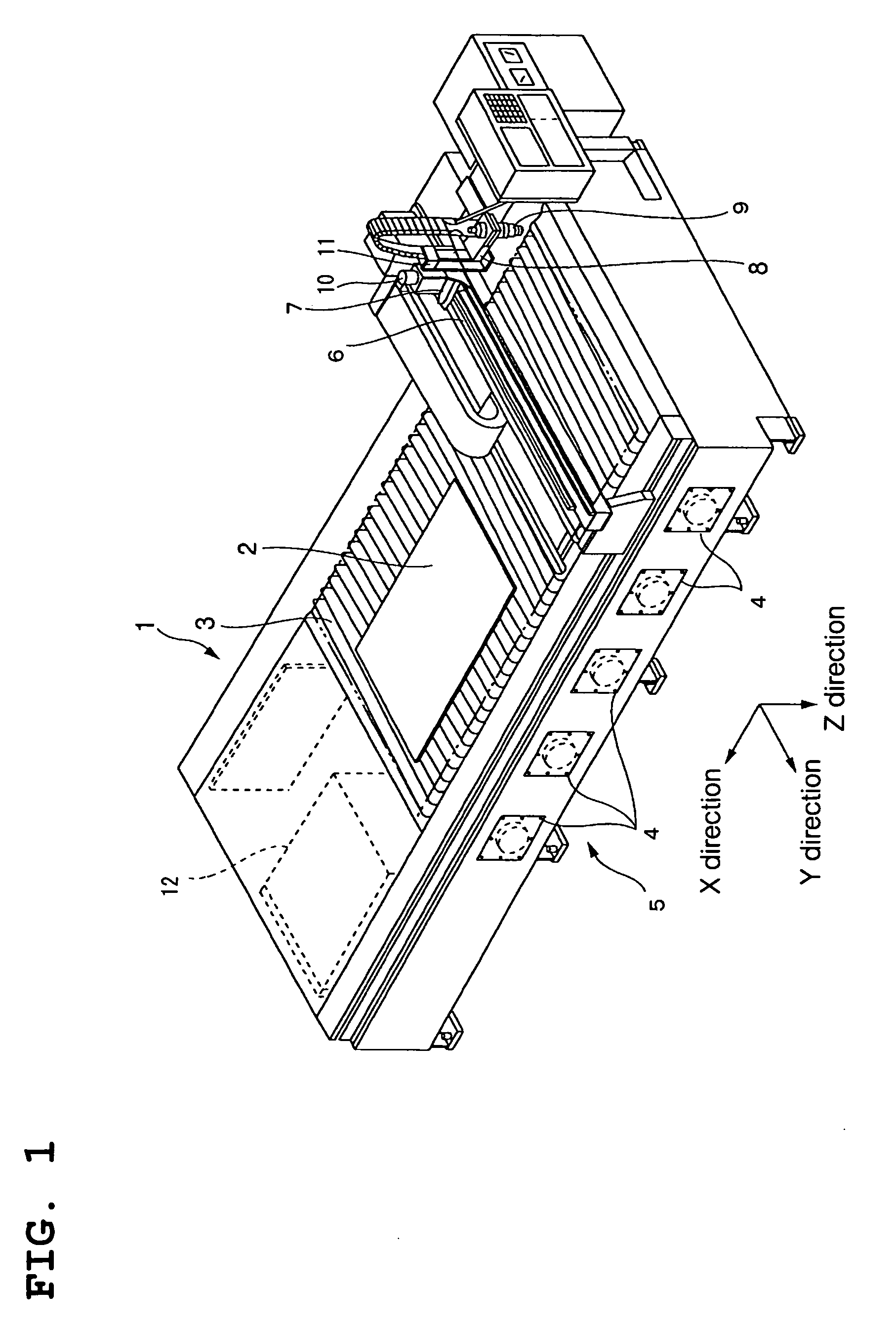
[0011]In accomplishing these and other objects, there has been firstly provided a thermal cutting machine for thermally cutting a workpiece, the machine comprising:

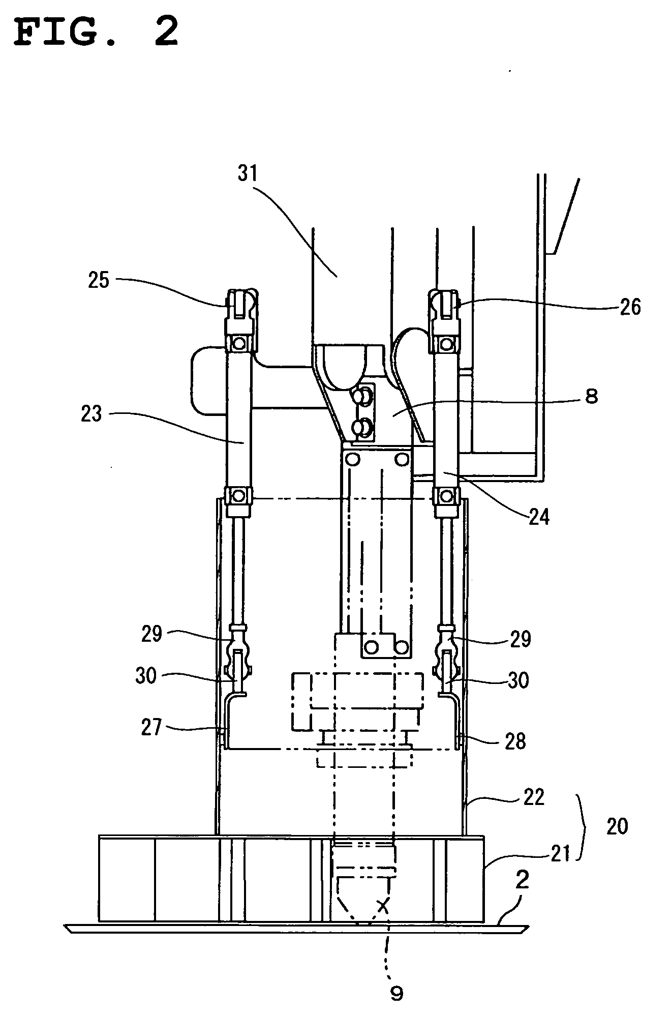
[0012]a torch for jetting out a plasma arc or a laser beam; and

[0013]a covering member for covering at least a specified angular range of the outer periphery of the torch,

[0014]wherein the covering member is constituted by a shielding plate provided with an opening portion (a first aspect of the invention).

[0015]The opening portion provided in the shielding plate may be a plurality of holes pierced in the shielding plate (a second aspect of the invention), a plurality of holes formed in a metal mesh (a third aspect of the invention), or a slit provided so as to extend upwardly from the lower end of the shielding plate (a fourth aspect of the invention).

[0016]Secondly, there is provided a thermal cutting machine for thermally cutting a workpiece, the machine comprising:

[0017]a torch for jetting out a plasma arc or a laser ...


PUM

PropertyMeasurementUnit
angleaaaaaaaaaa
anglesaaaaaaaaaa
pressureaaaaaaaaaa

Abstract

Adhesion and accumulation of spatter onto a covering member that encloses the outer periphery of a torch is minimized and flying of spatter is confined within a narrow area. To this end, a covering member for enclosing a specified angular range of the outer periphery of a plasma torch 9 is provided and an opening portion 35 is formed between every adjacent shielding plates 34 in the covering member.

Description

TECHNICAL FIELD[0001]The invention relates to a thermal cutting machine such as plasma cutting machines and laser cutting machines.BACKGROUND ART[0002]In known thermal cutting machines such as plasma cutting machines, molten material in the form of spatter (i.e., a splash of molten metal) flying from cut parts scatters in the surrounding area owing to the pressure of gas (e.g., plasma gas) ejected from the torch in the course of thermally cutting a workpiece. This not only adversely affects the work environment but also could cause fire hazard in the factory. Such spatter is generated, scattering into the environment particularly during a piercing process that is performed at a start of cutting a workpiece and mostly flies in a horizontal direction along the workpiece.[0003]As an attempt to solve the above problem, there have been proposed and practically used various techniques for preventing the flying of spatter by shielding around the torch during thermal cutting. One example of...

Claims


Application Information

Patent Timeline
Patent Type & Authority Applications(United States)
IPC IPC(8): B23K9/00
CPCB23K7/10B23K10/00B23K37/06B23K37/006B23K26/427B23K26/706B23K26/38B23K26/70
Inventor NISHIHARA, KENICHIOHNISHI, SATOSHI
Owner KOMATSU IND CORP
Why Eureka
Try Eureka