Linear drive transport system and method

a technology of linear drive and transport system, applied in the direction of conveyor parts, mechanical conveyors, non-mechanical conveyors, etc., can solve the problem of limited use of linear drives, and achieve the effect of facilitating the transfer of linear drive mover

Active Publication Date: 2016-06-09
ROCKWELL AUTOMATION TECH
View PDF4 Cites 30 Cited by
  • Summary
  • Abstract
  • Description
  • Claims
  • Application Information

AI Technical Summary

Benefits of technology

[0005]Present embodiments also include a shuttle system for a linear drive transport system. The shuttle system includes a conveyor configured to move along a path that is transverse to a plurality of linear drive tracks that are configured to transport a linear drive mover in one of a moving magnet configuration or a moving coil configuration. Further, the shuttle system includes a junction track dispo...

Problems solved by technology

This has caused limited employment of linear drives...

Method used


Image

  • Linear drive transport system and method
  • Linear drive transport system and method
  • Linear drive transport system and method

Examples


Embodiment Construction

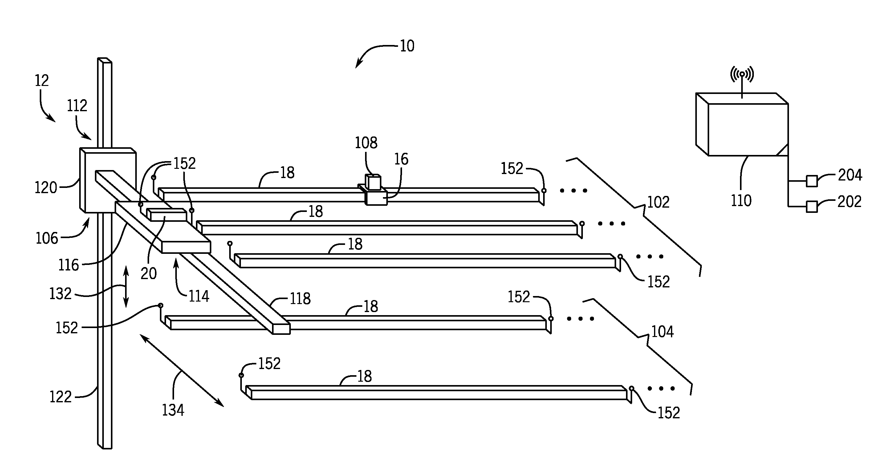
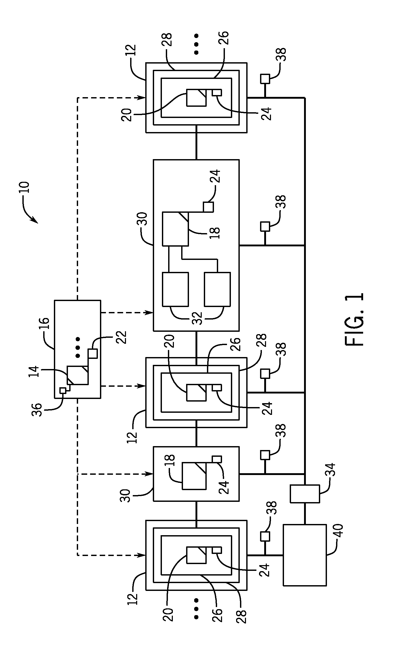
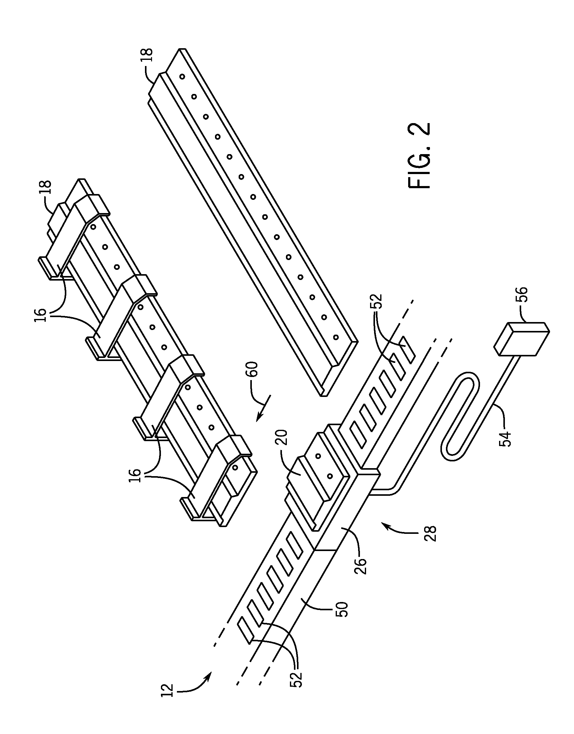
[0016]Present embodiments are directed to linear drive transport systems and components thereof. A linear drive transport system employs linear drives that utilize principles of electromagnetic propulsion to transport movers along a track. The linear drive transport system may employ a moving magnet configuration or a moving coil configuration. In both configurations, movers are impelled under the influence of electromagnetic force resulting from interaction between two electromagnetic fields (e.g., interaction between one or more electromagnetic coils and one or more permanent magnets). For example, in a moving magnet configuration, a mover may include an array of permanent magnets that are forced along as a result of interaction between magnetic fields of the array and magnetic fields generated by electromagnet coils in a track. Similarly, in a moving coil configuration, a mover may include one or more electromagnet coils and a track may include permanent magnets that cooperate to...


PUM


Abstract

Present embodiments include a linear drive transport system. The system includes a plurality of fixed tracks and a junction track disposed on a conveyor configured to align the junction track with each of the plurality of fixed tracks. The plurality of fixed tracks and the junction track include one of electromagnetic coils or permanent magnets arranged in series along the respective plurality of fixed tracks and the junction track. Further, present embodiments include a plurality of movers configured to move along the fixed tracks and configured to transition between each of the plurality of fixed tracks and the junction track when aligned, wherein the movers comprise the other of the electromagnetic coils or the permanent magnets.

Description

BACKGROUND[0001]The present disclosure is generally directed to linear drive transport systems and methods. More particularly, present embodiments are directed to systems and methods for conveyance management, including monitoring and control, with a linear drive transport system.[0002]A linear drive or linear motor generally includes an electromagnetic device that operates to provide motion along a path or “linear motion” rather than the rotary motion typically provided by a standard electric motor. In operation, a linear drive typically produces electromotive force in a conductor by changing a magnetic field about the conductor. Specifically, linear drives generally function based on interactions between electromagnets and permanent magnets. Coils of the electromagnets can be charged to create magnetic fields that interact with permanent magnets to provide motion. There are two fundamental linear drives categories, which may be referred to as moving magnet (or fixed coil) linear d...

Claims


Application Information

Patent Timeline
IPC IPC(8): B65G54/02
CPCB65G54/02B65G47/642B65G47/643B65G54/025B65G47/648
Inventor WERNERSBACH, GLEN C.JACOBS, KEITH G.HIGGINS, DEAN L.CRAVER, JAMES A.BOYLE, PETER T.
Owner ROCKWELL AUTOMATION TECH
Why Eureka
Try Eureka