Automobile

a technology for automobiles and motors, applied in the field of automobiles, can solve the problems of increasing and achieve the effects of suppressing a relatively large accelerating catalyst warm-up, and reducing the delay amount of ignition timing

Inactive Publication Date: 2016-06-09
TOYOTA JIDOSHA KK
View PDF0 Cites 8 Cited by
  • Summary
  • Abstract
  • Description
  • Claims
  • Application Information

AI Technical Summary

Benefits of technology

[0007]The automobile of this aspect delays the ignition timing of the engine in the case where the catalyst in the emission control apparatus of the engine is warmed up, compared with the ignition timing in the case where the catalyst is not warmed up. This accelerates warm-up of the catalyst. When the catalyst is warmed up, the delayed amount of the ignition timing is decreased with an increase in delay of the open-close timing of the intake valve. This suppresses a relatively large delayed amount of the ignition timing from being set at a relatively large delayed amount of the open-close timing of the intake valve (for example, at the most delayed open-close timing). This accordingly suppresses unstable combustion of the engine and suppresses an increase in output variation of the engine. As a result, this suppresses rattling-induced abnormal noise in a gear mechanism connected with the engine. In the description hereof, “case where the catalyst is warmed up” means that case that the temperature of the catalyst is lower than a predetermined temperature, and “case where the catalyst is not warmed up” means that the temperature of the catalyst is equal to or higher than the predetermined temperature.

Problems solved by technology

During a time duration from a start of the engine to completion of warm-up of the three-way catalyst, in a low loading range, this proposed automobile delays the open-close timing of the intake valve and increases the delayed amount of the ignition timing, compared with the ignition timing in a range other than the low loading range.

Method used


Image

  • Automobile
  • Automobile
  • Automobile

Examples


Embodiment Construction

[0022]The following describes some aspects of the invention with reference to embodiments.

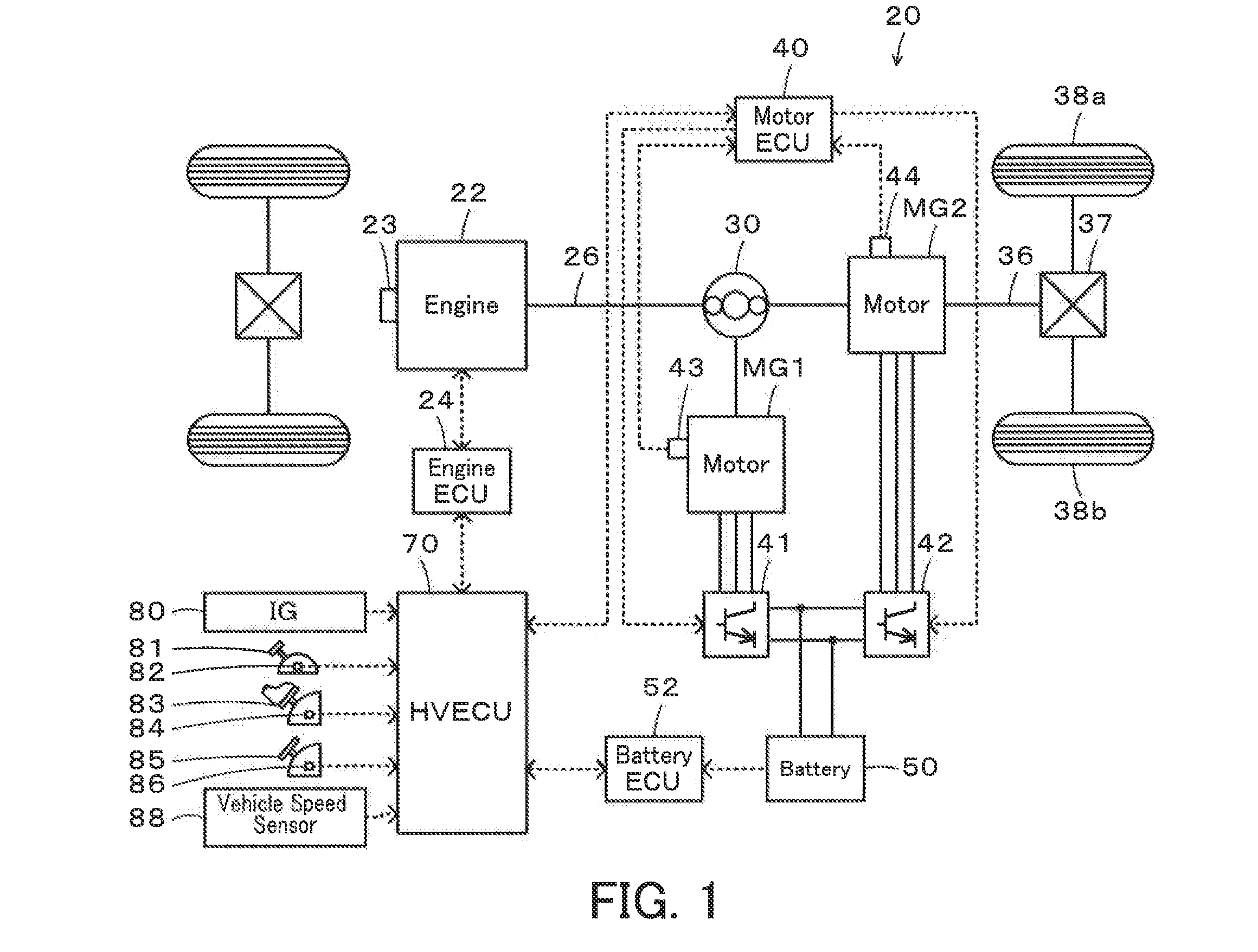
[0023]FIG. 1 is a configuration diagram illustrating the schematic configuration of a hybrid vehicle 20 according to one embodiment of the invention. As illustrated, the hybrid vehicle 20 of the embodiment includes an engine 22, a planetary gear 30, motors MG1 and MG2, inverters 41 and 42, a battery 50 and a hybrid electronic control unit (hereinafter referred to as HVECU) 70.

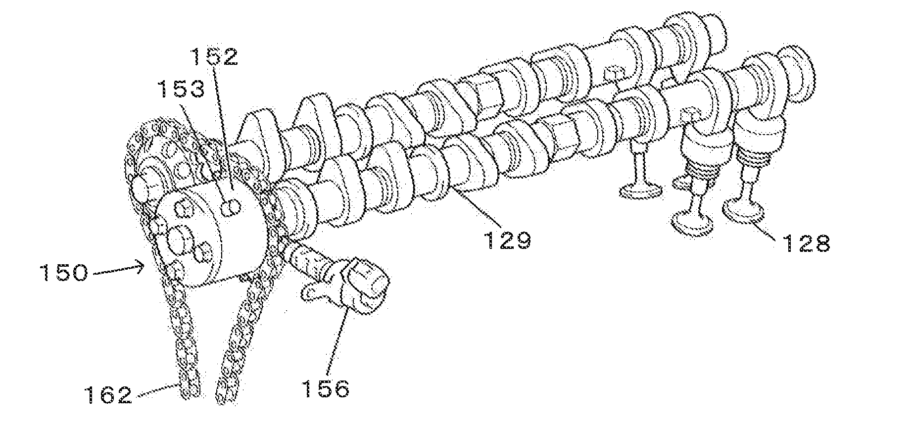
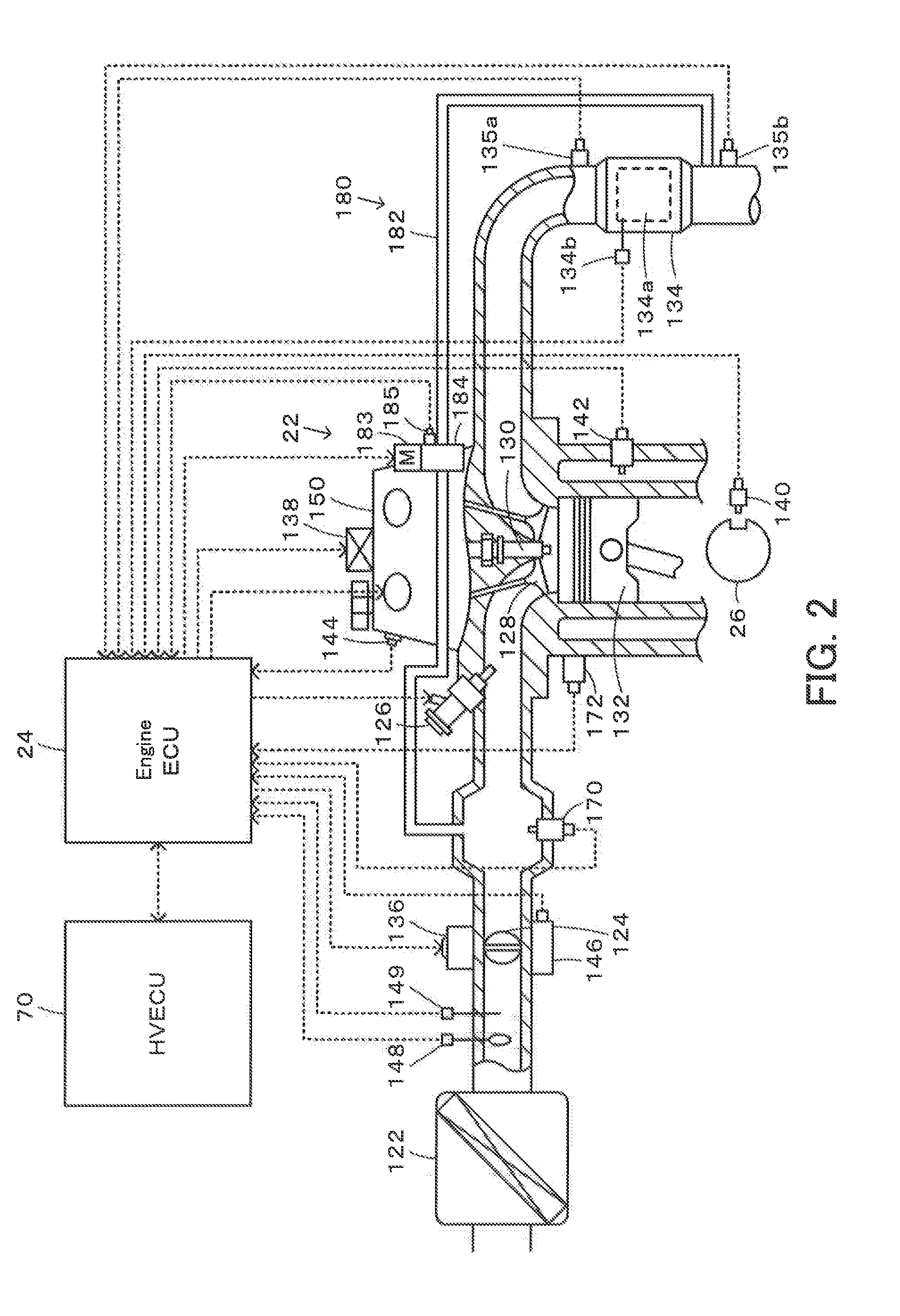
[0024]The engine 22 is configured as an internal combustion engine to use gasoline, light oil or the like as a fuel and output power. FIG. 2 is a configuration diagram illustrating the schematic configuration of the engine 22. As illustrated, the engine 22 takes in the air purified by an air cleaner 62 via a throttle valve 124 while injecting the fuel from a fuel injection valve 126 to mix the air with the fuel, and introduces the air-fuel mixture through an intake valve 128 into a combustion chamber. The engine 22 causes ...


PUM


Abstract

When a conversion catalyst in a catalytic converter is warmed up, a required efficiency ηtag is set such as to be within a range of less than 1 that is a value when the conversion catalyst is not warmed up and to increase with an increase in delay of an open-close timing VT of an intake valve (steps S130 to S160). A delayed amount of a target ignition timing IT* is decreased with an increase in required efficiency ηtag (closer to the value 1) (steps S170 and S180).

Description

TECHNICAL FIELD[0001]The present invention relates to an automobile and more specifically an automobile equipped with an engine.BACKGROUND ART[0002]A proposed automobile is equipped with an engine including a variable valve mechanism configured to change at least the open-close timing of an intake valve and a three-way catalyst configured to purify the exhaust emission (for example, Patent Literature 1). During a time duration from a start of the engine to completion of warm-up of the three-way catalyst, in a low loading range, this proposed automobile delays the open-close timing of the intake valve and increases the delayed amount of the ignition timing, compared with the ignition timing in a range other than the low loading range. This aims to accelerate activation of the three-way catalyst.SUMMARY OF INVENTIONTechnical Problem[0003]Setting a relatively large delayed amount of the ignition timing at a relatively large delayed amount of the open-close timing of the intake valve is...

Claims


Application Information

Patent Timeline
Patent Type & Authority Applications(United States)
IPC IPC(8): F02D41/02F02D13/02
CPCF02D13/0234F02D41/0255F01N3/20F01N3/2006F02P5/00B60W10/06B60W10/08F02P5/045F02P5/1502F02D13/0238F02D37/02F02D41/0002F02D2011/102F02D2013/0292F02D2041/001F02D2200/021F02D2200/0802F02D29/02F01L1/3442F01L2001/34433F01L2001/34469F01L2250/02F01L2800/00F01L2820/042F02P5/1504F02P5/1506F02P5/1508B60K6/445B60W2510/0676B60W2510/068B60W2530/12B60Y2300/474B60W20/16Y02T10/12Y02T10/40Y02T10/62
Inventor ENDO, HIROKIMARUYAMA, KENYAYAMAZAKI, MAKOTO
Owner TOYOTA JIDOSHA KK
Why Eureka
Try Eureka