Multi-tier limit-angle protection device

Active Publication Date: 2016-06-09
NAT CHUNG SHAN INST SCI & TECH
View PDF3 Cites 2 Cited by
  • Summary
  • Abstract
  • Description
  • Claims
  • Application Information

AI Technical Summary

Benefits of technology

The present invention aims to improve the design of limit switches by replacing the conventional contact-based switches with non-contact magnetic induction mechanisms. This simplifies the mechanism and reduces the costs associated with parts and components. The invention also provides a sophisticated limit-angle protection mechanism that can carry out multiple protection processes to ensure secure and stable protection. The invention integrates software and hardware to achieve a multi-tier limit-angle protection mechanism and utilizes magnetic sensing elements to assess the reliability of the potentiometer. Additionally, the invention involves integrating an analog magnetic field sensing chip and a digital magnetic field sensing chip to further reduce mechanism complexity and enhance the reliability of the products.

Problems solved by technology

Although a conventional mechanical stopper puts a restraint on the angle of rotation of the mechanism, it is incapable of protective power interruption, thereby causing damage to the mechanism or overloading the device under an overly large driving force.
But the special shape of the magnetic blocks has the following disadvantages: since the journey of the displacement of the magnetic blocks correlates with the size of the magnetic blocks, given a constant installation space, the larger the magnetic blocks, the less the remaining displacement; to achieve a relatively large range of motion, the required volume of the device must increase; what is more, US20040017187 discloses just a single limit-angle surveillance mechanism and thus still has room for improvement in security.

Method used


Image

  • Multi-tier limit-angle protection device
  • Multi-tier limit-angle protection device
  • Multi-tier limit-angle protection device

Examples


Embodiment Construction

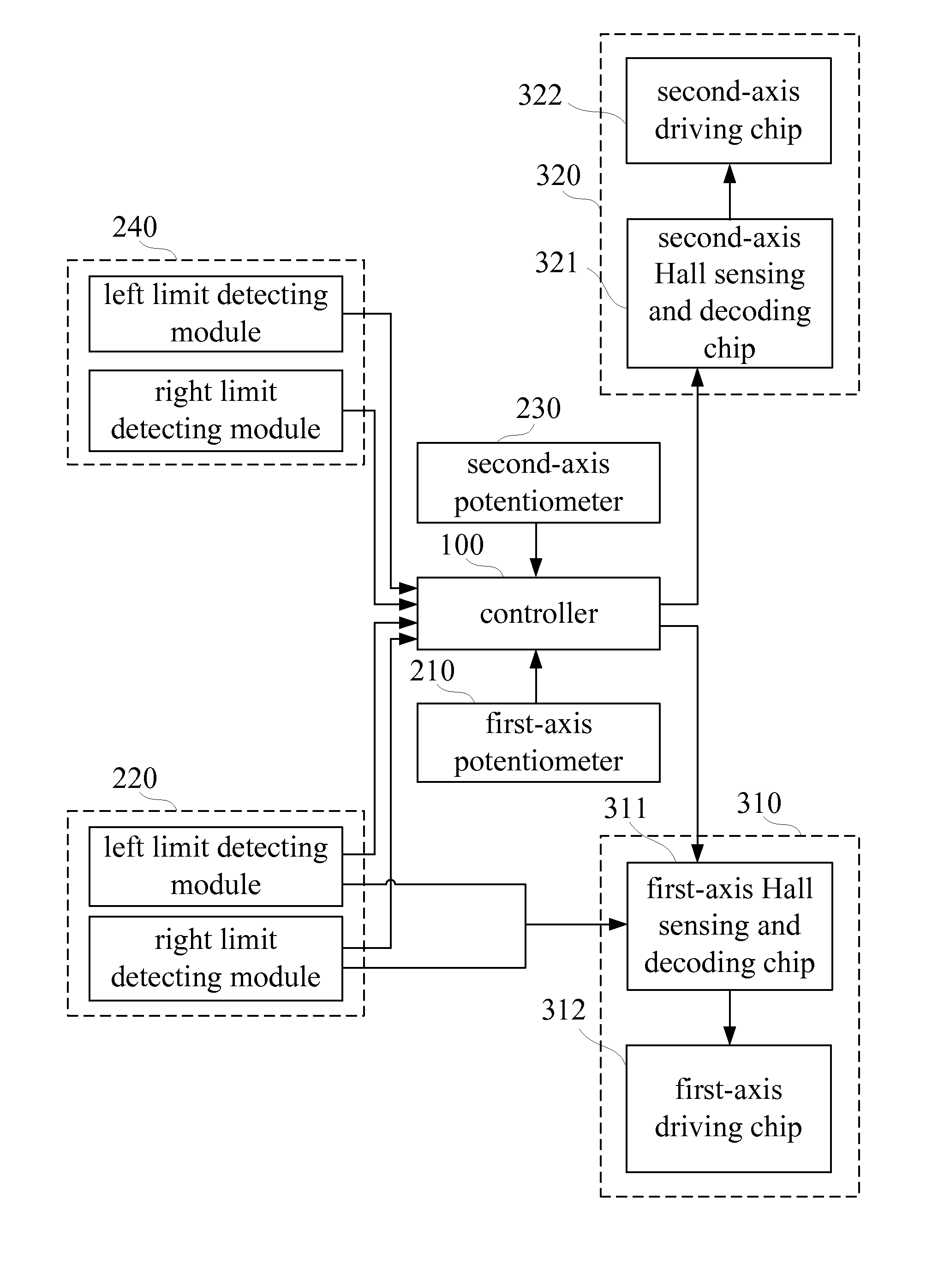
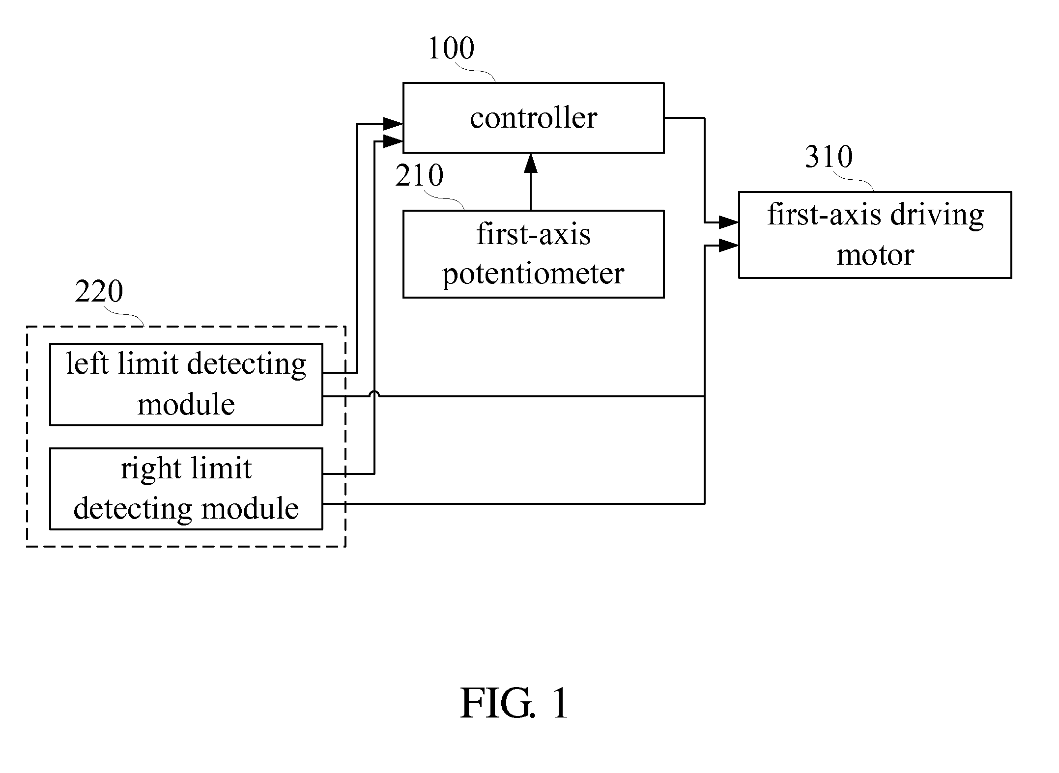
[0025]Referring to FIG. 1, there is shown a function block diagram of a multi-tier limit-angle protection device according to an embodiment of the present invention. According to the present invention, in an embodiment, a multi-tier limit-angle protection device for detecting a rotation angle about a first axis of a driving apparatus comprises a first-axis potentiometer 210, a first-axis limit-angle detecting module 220, and a controller 100. The controller 100 controls the operation of a first-axis driving motor 310 of the driving apparatus. Examples of the controller 100 include a micro control unit (MCU) with a built-in single chip. The first-axis limit-angle detecting module 220 comprises a left limit detecting module and a right limit detecting module which are also known as limit-angle detecting modules and adapted to detect a positive limit-angle and a negative limit-angle, respectively.

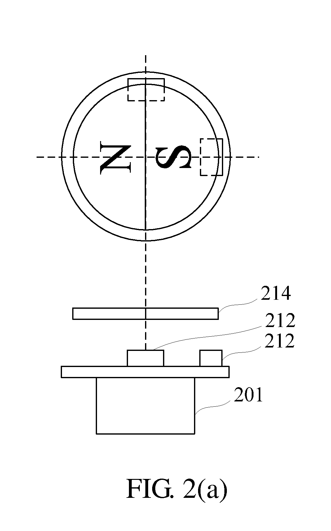
[0026]Referring to FIG. 2 (a), there is shown a schematic view of a first-tier limit-angle...


PUM


Abstract

A multi-tier limit-angle protection device detects a rotation angle about a rotation axis of a driving apparatus to thereby control the operation of a driving motor of the driving apparatus. The multi-tier limit-angle protection device includes a first-axis potentiometer for generating a first-axis sensing signal, a first-axis limit-angle detecting module for generating a first-axis confirming signal, and a controller. The controller effectuates a first tier protection mechanism by determining whether a limit angle of the rotation axis is exceeded according to the first-axis sensing signal, effectuates a second tier protection mechanism by determining whether the first-axis potentiometer is operating well according to a first-axis confirming signal, and effectuates a third tier protection mechanism through its control over the driving motor. The multi-tier limit-angle protection device features integration of software and hardware to thereby preclude mechanism complexity and provide a multi-tier limit-angle protection mechanism.

Description

FIELD OF TECHNOLOGY[0001]The present invention relates to multi-tier limit-angle protection devices, and more particularly, to a limit-angle protection device for use with a rotation mechanism with limited stroke to prevent a driven apparatus from suffering damage which might otherwise happen if the angle of rotation of the mechanism exceeds the limit.BACKGROUND[0002]A rotation mechanism with limited stroke usually operates in conjunction with a limit-angle protection device to prevent a driven apparatus from suffering damage which might otherwise happen if the angle of rotation of the mechanism exceeds the limit. Although a conventional mechanical stopper puts a restraint on the angle of rotation of the mechanism, it is incapable of protective power interruption, thereby causing damage to the mechanism or overloading the device under an overly large driving force.[0003]A conventional limit switch applies to the installation of a rotation mechanism. Once it approaches an angular lim...

Claims


Application Information

Patent Timeline
IPC IPC(8): G01D5/14G01B7/30
CPCG01B7/30G01D5/145
Inventor WU, RUH-HUACHANG, CHUNG-TSENG
Owner NAT CHUNG SHAN INST SCI & TECH
Why Eureka
Try Eureka