Tool for releasing engaged state of optical connector

Inactive Publication Date: 2016-06-09
THE FUJIKURA CABLE WORKS LTD
View PDF1 Cites 14 Cited by
  • Summary
  • Abstract
  • Description
  • Claims
  • Application Information

AI Technical Summary

Benefits of technology

[0008]With the present invention, an engaged state of an

Problems solved by technology

If, however, there are other members (e.g. elements mounted on the substrate) around the receptacle, it may be difficult to rel

Method used


Image

  • Tool for  releasing engaged state of optical connector
  • Tool for  releasing engaged state of optical connector
  • Tool for  releasing engaged state of optical connector

Examples


embodiments

[0018]{Overall Configuration}

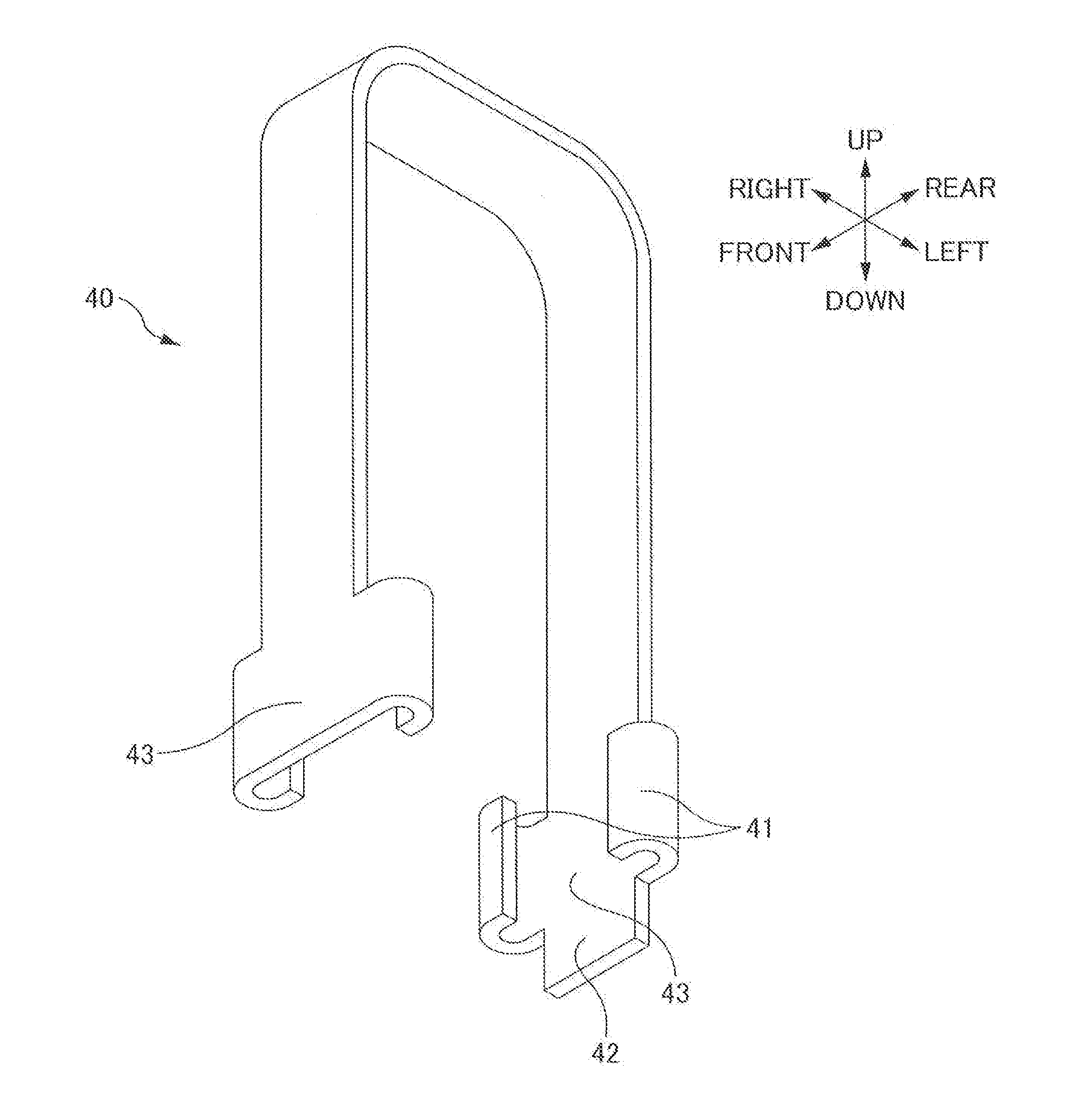
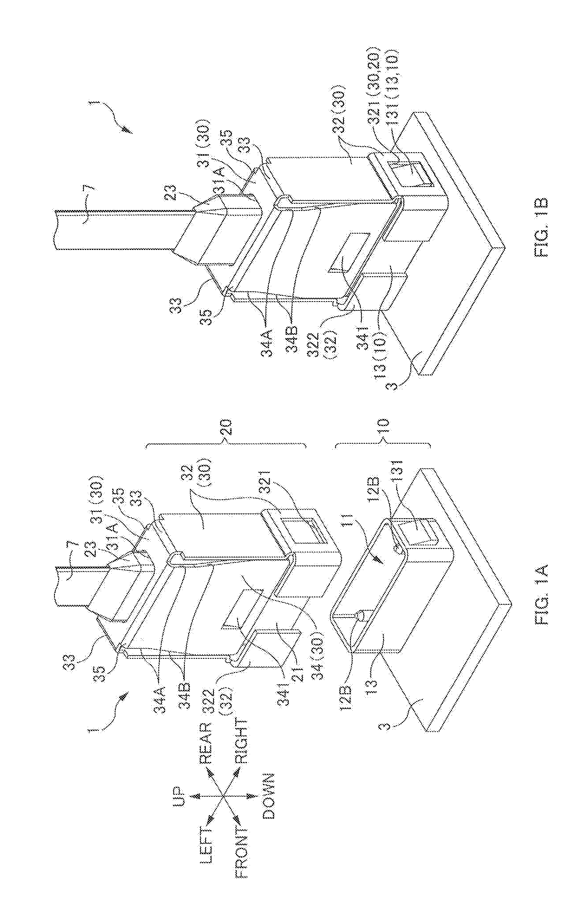
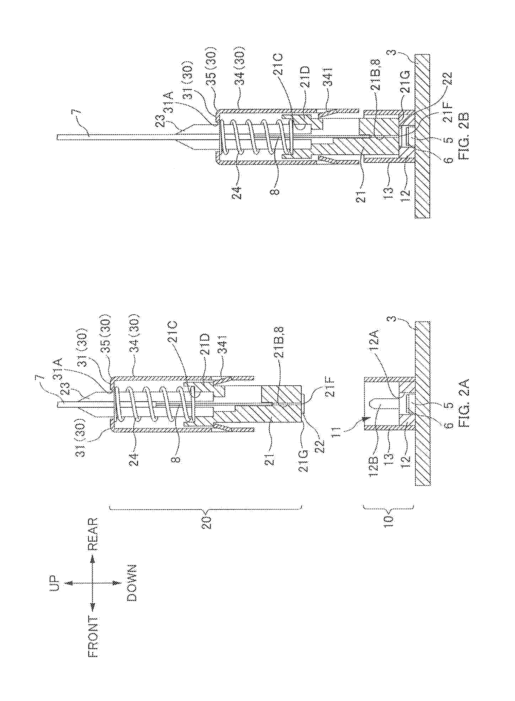
[0019]FIGS. 1A and 1B are perspective views of an optical connector device 1. FIG. 1A is a perspective view before connection of an optical connector 20. FIG. 1B is a perspective view when the optical connector 20 has been connected. FIGS. 2A and 2B are cross-sectional views of the optical connector device 1. FIG. 2A is a cross-sectional view before connection of the optical connector 20. FIG. 2B is a cross-sectional view when the optical connector 20 has been connected. In FIGS. 2A and 2B, guide parts 322 on the lower side of the optical connector 20 are not illustrated for the sake of simplifying the figures.

[0020]In the following description, the various directions are defined as illustrated in FIG. 1A. That is, the direction perpendicular to the substrate 3 is the “up / down direction”; the side toward the receptacle 10 as viewed from the substrate is “up”, and the opposite side is “down”. The width direction of the optical fiber tape 7 (the direction ...


PUM


Abstract

Disclosed is a tool for releasing an engaged state in which a receptacle-side engagement section formed on a side surface of a receptacle provided on a substrate is engaged with a connector-side engagement section of an optical connector that is attachable to and detachable from the receptacle. The tool includes: release claws to be inserted into respective gaps, each gap being formed between a member arranged between a pair of engagement side plate parts each being provided with the connector-side engagement section, and each engagement side plate part; and a guide part that comes into opposition with a side surface of the optical connector or the receptacle. By bringing the guide part into opposition with the side surface and sliding the release claws toward the substrate, the engagement side plate parts are spread outward by the release claws and the engaged state is released.

Description

TECHNICAL FIELD[0001]The present invention relates to a tool for releasing an engaged state of an optical connector.BACKGROUND ART[0002]A technique known in the art involves positioning a ferrule, which holds an end section of an optical fiber, with respect to a receptacle, which is provided on a substrate, by means of positioning sections (a positioning pin and a positioning hole), and thereby optically connecting the optical fiber and a photoelectric conversion element provided on the substrate. For example, Patent Literature 1 discloses a technique in which a ferrule (reference number 20 in Patent Literature 1) and a receptacle (reference number 80 in Patent Literature 1) provided on a substrate are positioned with respect to one another to optically connect an optical fiber and a photoelectric conversion element provided on the substrate.[0003]In Patent Literature 1, the ferrule is fixed by fixing a fixing member (reference number 60 in Patent Literature 1) which houses the ferr...

Claims


Application Information

Patent Timeline
IPC IPC(8): G02B6/38B25B27/00
CPCB25B27/00G02B6/3898G02B6/3821G02B6/3883G02B6/3893G02B6/3897G02B6/4292G02B6/36G02B6/42
Inventor NISHIMURA, AKITO
Owner THE FUJIKURA CABLE WORKS LTD
Why Eureka
Try Eureka