Tire inflation pressure detection device
a technology of tire inflation and detection device, which is applied in the direction of instruments, tyre measurements, vehicle components, etc., can solve the problems of increasing the current consumption of the vehicle, and affecting the stability of the vehicl
- Summary
- Abstract
- Description
- Claims
- Application Information
AI Technical Summary
Benefits of technology
Problems solved by technology
Method used
Image
Examples
first embodiment
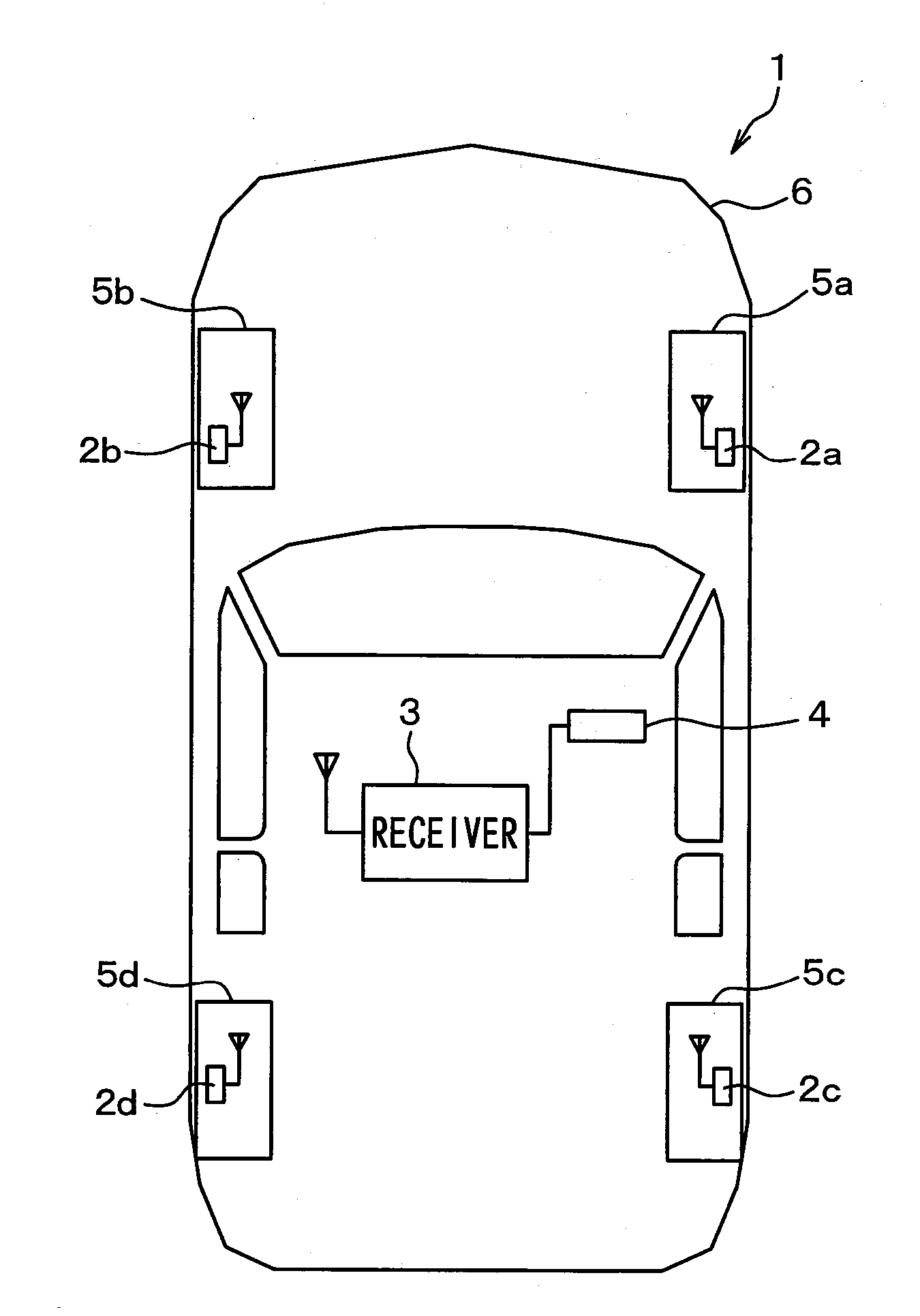
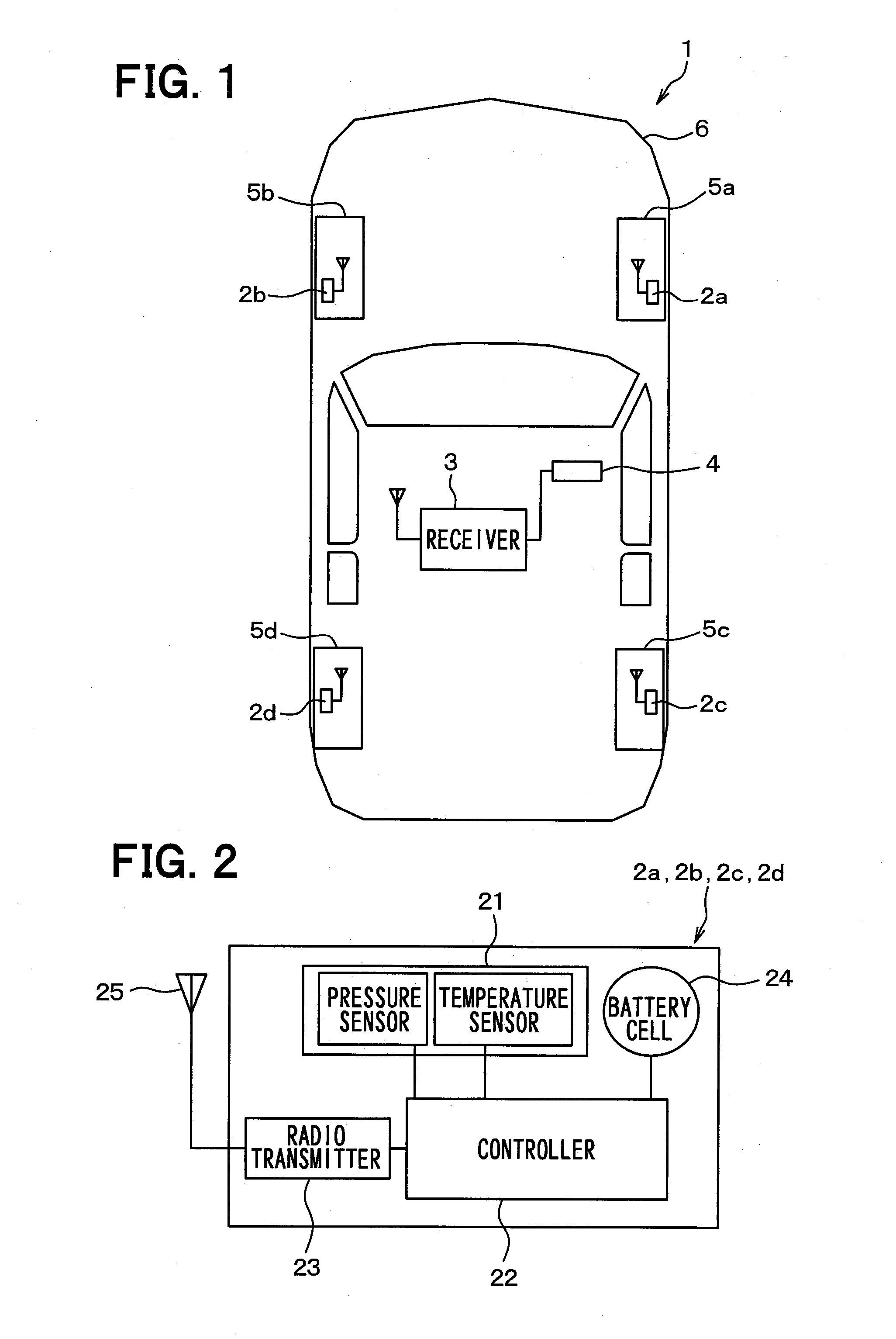
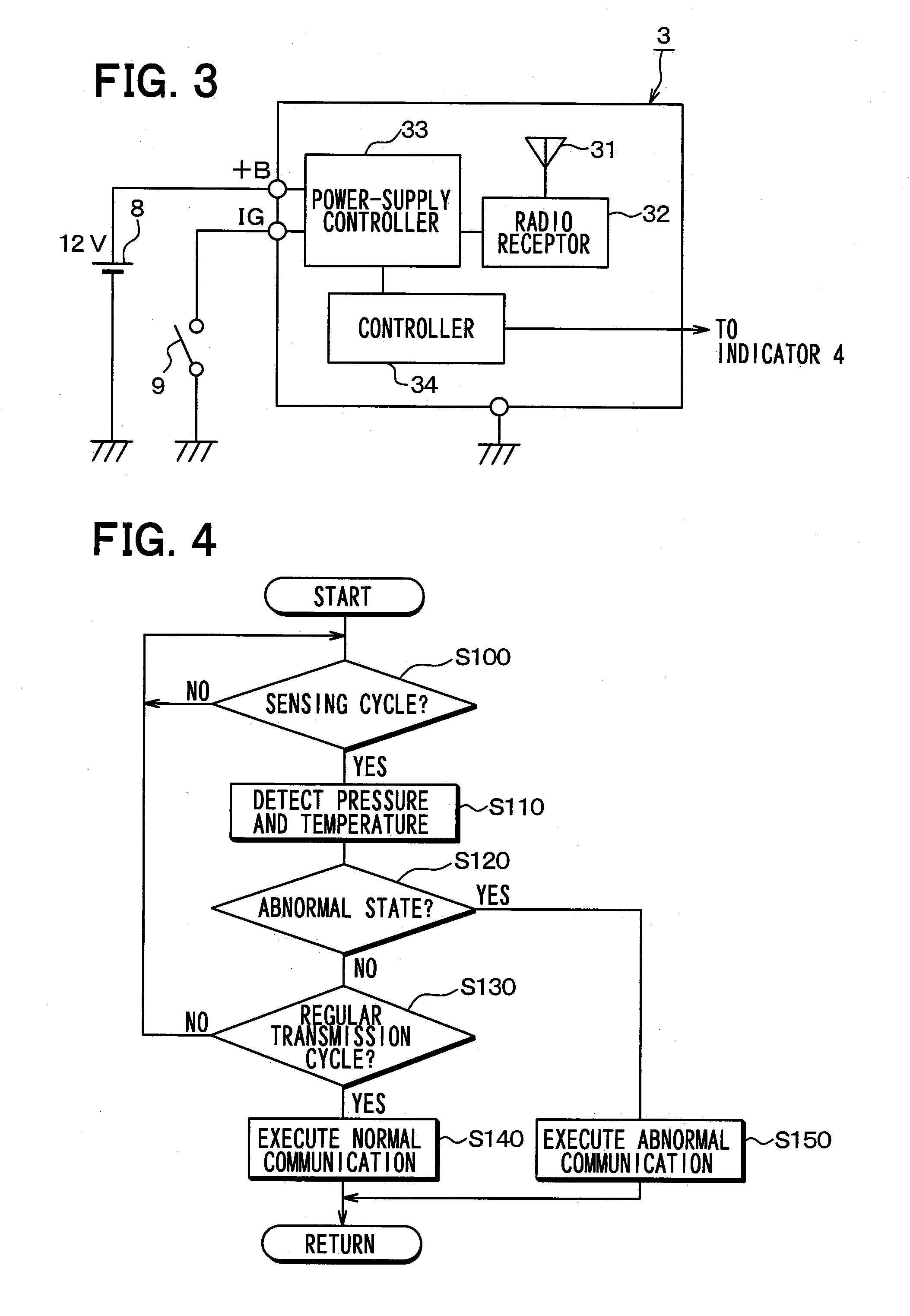
[0023]A first embodiment of the present disclosure will be described with reference to FIG. 1 through FIG. 5. In FIG. 1, an upper side of the sheet surface is a front side of a vehicle 1, a lower side of the sheet surface is a rear side of the vehicle 1, and a right-left direction of the sheet surface is a right-left direction of the vehicle.
[0024]A tire inflation pressure detection device shown in FIG. 1 is attached to the vehicle 1 and formed of transmitters 2a through 2d, a receiver 3, and an indicator 4.
[0025]As is shown in FIG. 1, the transmitters 2a through 2d are attached, respectively, to wheels 5a through 5d of the vehicle 1, and detect air pressures of tires attached to the wheels 5a through 5d. The transmitters 2a through 2d also store data of detection signals indicting detection results into frames and transmit the frames. The receiver 3 is attached to a vehicle body 6 of the vehicle 1, and receives the frames transmitted from the transmitters 2a through 2d and also det...
second embodiment
[0059]A second embodiment of the present disclosure will be described. In the present embodiment, a shortest period is defined for the reception enable period T2 described in the first embodiment above. Because the rest is the same as the first embodiment above, a description will be given only to a difference from the first embodiment above.
[0060]A dark current can be increased by activating a receiver 3 while an IG 9 is OFF. It is therefore preferable to shorten a reception enable period T2 which is a period during which the receiver 3 is activated and becomes capable of receiving frames because the dark current can be reduced. However, by making the reception enable period T2 too short, when transmitters 2a through 2d transmit frames upon detection of the occurrence of a decrease of a tire inflation pressure, the receiver 3 may possibly fail to receive the frames accurately.
[0061]In order to eliminate such an inconvenience, the present embodiment is configured so as to set the re...
third embodiment
[0063]A third embodiment of the present disclosure will be described. In the present embodiment, a more preferable period is defined for the reception enable period T2 used in the first embodiment above. Because the rest is the same as the first embodiment above, a description will be given only to a difference from the first embodiment above.
[0064]The second embodiment above has described a case where the reception enable period T2 is shortened by giving consideration to a reduction of the dark current while the IG 9 is OFF. However, by making the reception enable period T2 too short, the receiver 3 may possibly fail to receive frames transmitted from the transmitters 2a through 2d when a tire inflation pressure is normal while the IG 9 is OFF.
[0065]In order to eliminate such an inconvenience, the present embodiment is configured so as to set a reception enable period T2 to a time as long as or longer than a regular transmission cycle T1 of frames plus a frame length T6 of one fram...
PUM
 Abstract
Description
Claims
Application Information
 - R&D
- Intellectual Property
- Life Sciences
- Materials
- Tech Scout
- Unparalleled Data Quality
- Higher Quality Content
- 60% Fewer Hallucinations
Browse by: Latest US Patents, China's latest patents, Technical Efficacy Thesaurus, Application Domain, Technology Topic, Popular Technical Reports.
© 2025 PatSnap. All rights reserved.Legal|Privacy policy|Modern Slavery Act Transparency Statement|Sitemap|About US| Contact US: help@patsnap.com


