Tire inflation pressure detection device

a technology of tire inflation and detection device, which is applied in the direction of instruments, tyre measurements, vehicle components, etc., can solve the problems of increasing the current consumption of the vehicle, and affecting the stability of the vehicl

Active Publication Date: 2017-10-03
DENSO CORP
View PDF13 Cites 5 Cited by
  • Summary
  • Abstract
  • Description
  • Claims
  • Application Information

AI Technical Summary

Benefits of technology

[0008]The present disclosure has an object to provide a tire inflation pressure detection device not only capable of notifying a driver of a decrease of a tire inflation pressure more promptly when an IG is turned ON, but also capable of restricting an increase of a dark current while a vehicle is stopped.
[0010]Owing to the configuration as above, the receiver becomes capable of receiving the frames in every intermittent cycle even while the IG is OFF. Upon detection of the occurrence of a decrease of the tire inflation pressure, the transmitter transmits the frames in succession at a short frame transmission interval during the emergency transmission period, which is a period longer than the intermittent cycle, at a high frequency. Hence, even when the transmitter detects the occurrence of a decrease of the tire inflation pressure while the IG is OFF, the frames can be received at the receiver in a reliable manner and a warning on the occurrence of a decrease of the tire inflation pressure can be given to a driver more promptly when the IG is turned ON.

Problems solved by technology

However, by merely configuring the system to perform a tire inflation pressure detection while the IG is OFF and while the IG is ON in the same manner, a dark current while the vehicle is stopped (current consumed while the vehicle is stopped) increases markedly and the battery runs out.

Method used


Image

  • Tire inflation pressure detection device
  • Tire inflation pressure detection device
  • Tire inflation pressure detection device

Examples


first embodiment

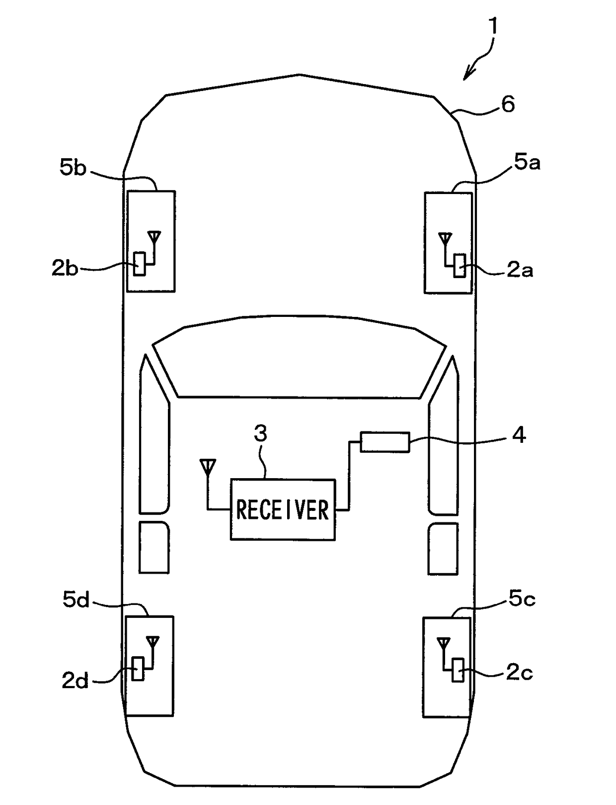
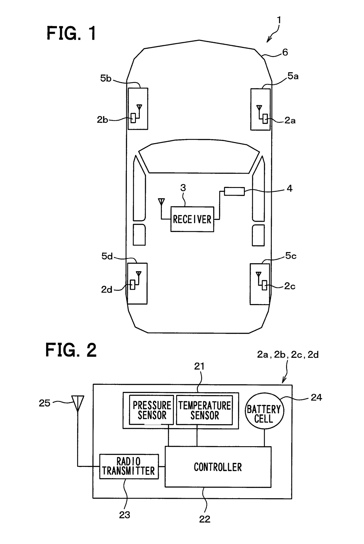
[0023]A first embodiment of the present disclosure will be described with reference to FIG. 1 through FIG. 5. In FIG. 1, an upper side of the sheet surface is a front side of a vehicle 1, a lower side of the sheet surface is a rear side of the vehicle 1, and a right-left direction of the sheet surface is a right-left direction of the vehicle.

[0024]A tire inflation pressure detection device shown in FIG. 1 is attached to the vehicle 1 and formed of transmitters 2a through 2d, a receiver 3, and an indicator 4.

[0025]As is shown in FIG. 1, the transmitters 2a through 2d are attached, respectively, to wheels 5a through 5d of the vehicle 1, and detect air pressures of tires attached to the wheels 5a through 5d. The transmitters 2a through 2d also store data of detection signals indicting detection results into frames and transmit the frames. The receiver 3 is attached to a vehicle body 6 of the vehicle 1, and receives the frames transmitted from the transmitters 2a through 2d and also det...

second embodiment

[0059]A second embodiment of the present disclosure will be described. In the present embodiment, a shortest period is defined for the reception enable period T2 described in the first embodiment above. Because the rest is the same as the first embodiment above, a description will be given only to a difference from the first embodiment above.

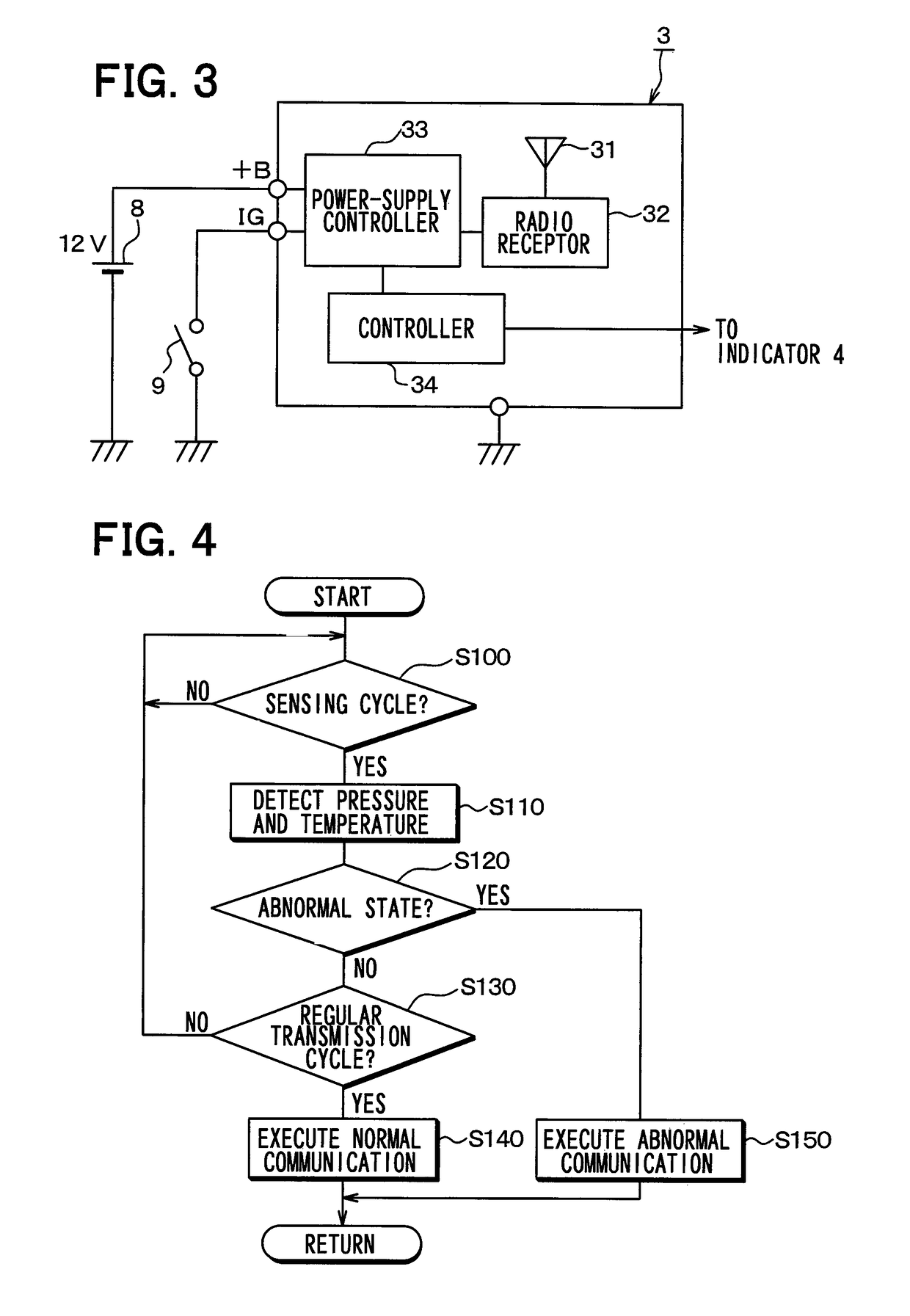
[0060]A dark current can be increased by activating a receiver 3 while an IG 9 is OFF. It is therefore preferable to shorten a reception enable period T2 which is a period during which the receiver 3 is activated and becomes capable of receiving frames because the dark current can be reduced. However, by making the reception enable period T2 too short, when transmitters 2a through 2d transmit frames upon detection of the occurrence of a decrease of a tire inflation pressure, the receiver 3 may possibly fail to receive the frames accurately.

[0061]In order to eliminate such an inconvenience, the present embodiment is configured so as to set the re...

third embodiment

[0063]A third embodiment of the present disclosure will be described. In the present embodiment, a more preferable period is defined for the reception enable period T2 used in the first embodiment above. Because the rest is the same as the first embodiment above, a description will be given only to a difference from the first embodiment above.

[0064]The second embodiment above has described a case where the reception enable period T2 is shortened by giving consideration to a reduction of the dark current while the IG 9 is OFF. However, by making the reception enable period T2 too short, the receiver 3 may possibly fail to receive frames transmitted from the transmitters 2a through 2d when a tire inflation pressure is normal while the IG 9 is OFF.

[0065]In order to eliminate such an inconvenience, the present embodiment is configured so as to set a reception enable period T2 to a time as long as or longer than a regular transmission cycle T1 of frames plus a frame length T6 of one fram...


PUM

PropertyMeasurementUnit
pressureaaaaaaaaaa
frequencyaaaaaaaaaa
power-supply stateaaaaaaaaaa

Abstract

In a tire inflation pressure detection device, a receiver functions such that, when an ignition switch is on, power is generated by a power supply controller to set the power supply state of the receiver to one in which frame reception is enabled to detect the inflation pressure of a tire, and such that, when the IG is off, in each predetermined intermittent cycle power is generated by the power supply controller to set the power supply state of the receiver to one in which frame reception is enabled to detect the inflation pressure of the tire. A transmitter determines whether a decrease in tire inflation pressure occurs, and when the decrease occurs, the transmitter transmits frames more frequently than before the occurrence of the decrease in tire inflation pressure at a shorter frame transmission time interval than a regular transmission cycle during a high-frequency transmission period.

Description

CROSS REFERENCE TO RELATED APPLICATIONS[0001]This application is a U.S. National Phase Application under 35 U.S.C. 371 of International Application No. PCT / JP2014 / 003180 filed on Jun. 16, 2014 and published in Japanese as WO 2015 / 015692 A1 on Feb. 5, 2015. This application is based on and claims the benefit of priority from Japanese Patent Application No. 2013-159439 filed on Jul. 31, 2013 and Japanese Patent Application No. 2014-100691 filed on May 14, 2014. The entire disclosures of all of the above applications are incorporated herein by reference.TECHNICAL FIELD[0002]The present disclosure relates to a direct tire inflation pressure detection device.BACKGROUND ART[0003]A direct tire inflation pressure detection device is one type of tire inflation pressure detection device in the related art. The direct tire inflation pressure detection device is formed by directly attaching transmitters each including a sensor, such as a pressure sensor, to tired-wheels side and attaching an an...

Claims


Application Information

Patent Timeline
Patent Type & Authority Patents(United States)
IPC IPC(8): B60C23/04G01L17/00
CPCB60C23/0445B60C23/0455B60C23/0462G01L17/00
Inventor OKADA, NORIAKIWATABE, NOBUYAMORI, MASASHI
Owner DENSO CORP
Why Eureka
Try Eureka