Tire inflation pressure detecting device for vehicle

a tire inflation pressure and detection device technology, applied in vehicle tyre testing, vehicles, instruments, etc., can solve the problems of not being able to recognize which of the four tires is subject to a reduction in tire inflation pressure, requiring lots of rewriting, and being difficult to identify which of the tires corresponds to the received tire inflation pressure data. achieve the effect of simple structure and reduce tire inflation pressur

Inactive Publication Date: 2006-11-28
YAZAKI CORP
View PDF11 Cites 2 Cited by
  • Summary
  • Abstract
  • Description
  • Claims
  • Application Information

AI Technical Summary

Benefits of technology

[0008]Under the circumstances, it is therefore an object of the present invention to provide a tire inflation pressure detecting device which is simple in structure and which is capable of identifying a tire having a reduced tire inflation pressure.
[0011]Additionally, since the transmitting intervals of the pressure data are different from each other every tire, it is possible to prevent an interference among the pressure data transmitted from the plural transmitters, whereby the reception of the pressure data can be accomplished with high accuracy.
[0017]Then, owing to the provision of the outside trigger, it is possible to accomplish an operator's work for the above modification with ease.
[0021]In this case, due to the positioning of the antennas close to the transmitting units, the receipt sensitivity of the pressure data is improved with high accuracy.

Problems solved by technology

In the tire inflation pressure detecting device, however, it is impossible to identify which of the tires corresponds to the received tire inflation pressure data.
In detail, since the receiver is adapted so as to receive the tire inflation pressure data transmitted from the transmitters installed in four tires, if the tire inflation pressure is reduced, it is impossible to recognize which of the four tires is subjected to a reduction in tire inflation pressure.
Additionally, since the compliance relationship between the identification codes on the transmitters' side and the identification codes stored in the EEPROM would collapse at a “tire-rotation” where the conventional positions of the tires are modified in view of improving their lives, it is necessary to rewrite the identification codes stored in the EEPROM, requiring lots of labor for rewriting them.
Also in this case, however, the tire inflation pressure detecting device would be large sized while causing the manufacturing cost to be elevated.

Method used


Image

  • Tire inflation pressure detecting device for vehicle
  • Tire inflation pressure detecting device for vehicle
  • Tire inflation pressure detecting device for vehicle

Examples


Embodiment Construction

[0032]Embodiments of the present invention will be described with reference to the accompanying drawings.

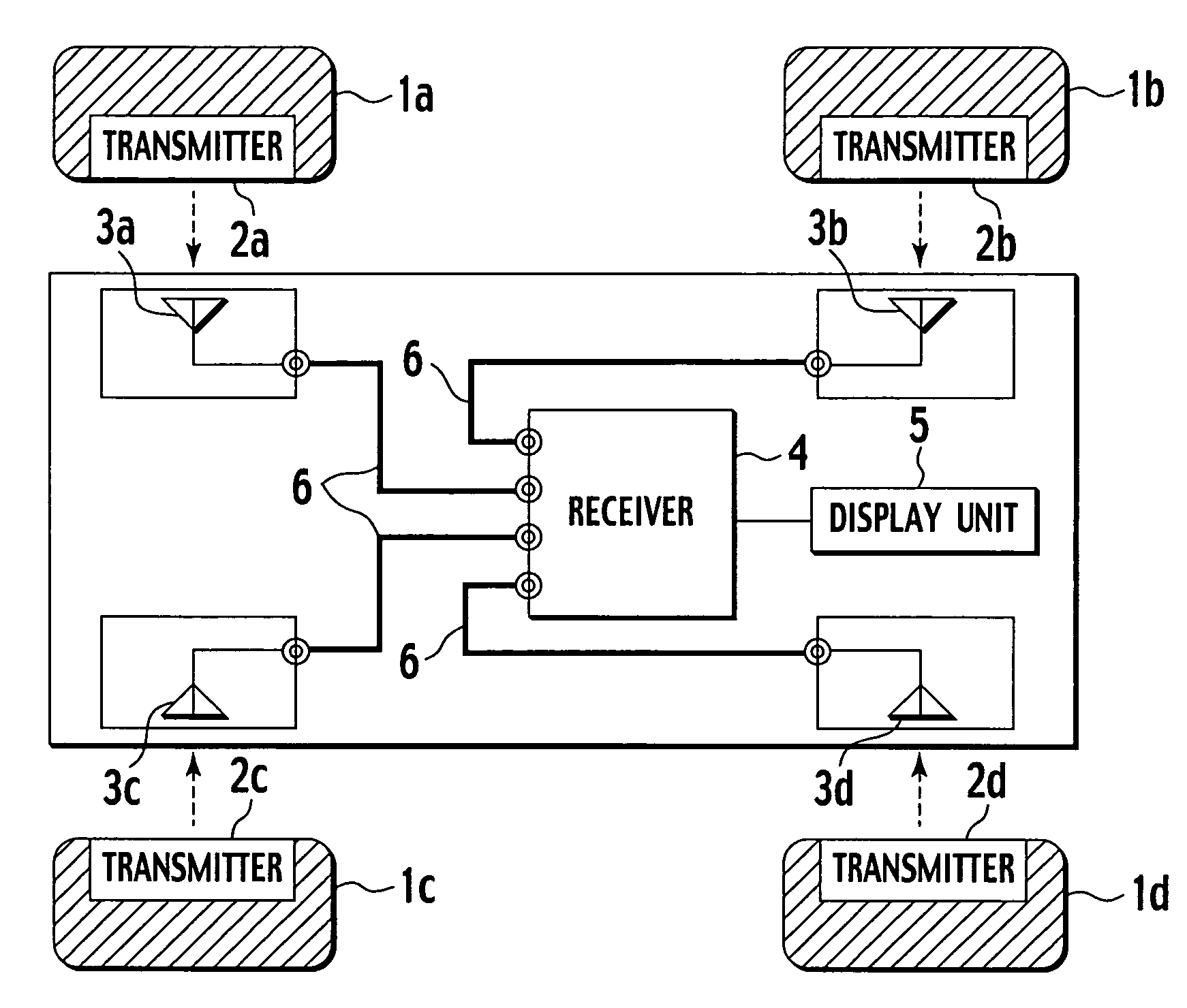
[0033]FIG. 1 is a block diagram showing the constitution of a tire inflation pressure detecting device in accordance with the first embodiment of the present invention. In FIG. 1, the tire inflation pressure detecting device includes transmitters (i.e. the transmitting units of the invention) 2a to 2d provided in four tires 1a to 1d of a vehicle respectively and antennas 3a to 3d arranged in the vicinity of the tires 1a to 1d respectively.

[0034]A vehicle body is provided, at an appropriate position thereof, with a receiver 4 which is connected to the antennas 3a to 3d through coaxial cables 6. Further, the vehicle body is equipped with a display unit 5 that displays the pressure data received by the receiver (i.e. the receiving unit of the invention) 4 to a passenger of the vehicle.

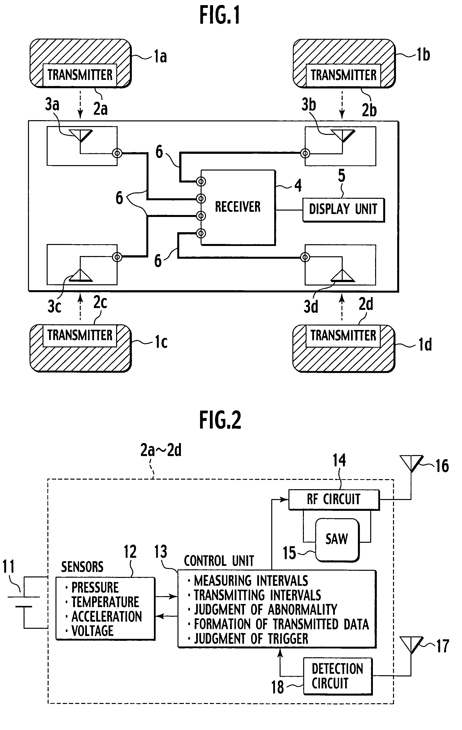
[0035]FIG. 2 is a block diagram showing each of the transmitters 2a to 2d provided in the tires 1a ...


PUM

PropertyMeasurementUnit
timeaaaaaaaaaa
timeaaaaaaaaaa
inflation pressureaaaaaaaaaa

Abstract

A tire inflation pressure detecting device includes sensors provided in respective tires of a vehicle to detect various kinds of measured data involving a tire inflation pressure, transmitters for transmitting the measured data and a receiver for receiving the measured data transmitted from the transmitters. In operation, each of the transmitters of the tires transmits the measured data plural times at certain transmitting intervals in a predetermined cycle. Among the transmitters, the respective transmitting intervals are different from each other.

Description

BACKGROUND OF THE INVENTION[0001]The present invention relates to a tire inflation pressure detecting device for detecting tire inflation pressure of a vehicle and particularly, it relates to a technique for specifying respective positions of the tires.[0002]There has been proposed and practically used a tire inflation pressure detecting device that detects tire inflation pressures of a vehicle at it traveling and provides resulting pressure information to a passenger in the vehicle in real time.[0003]The tire inflation pressure detecting device in an earlier art has pneumatic sensors each arranged in respective tires of the vehicle to detect respective tire inflation pressures, transmitters each arranged in the tires to transmit so-obtained tire inflation pressure data to the outside and a receiver arranged in a vehicle body to receive the tire inflation pressure data. Then, the tire inflation pressure data received by the receiver is displayed on display means to the passenger.[00...

Claims


Application Information

Patent Timeline
Patent Type & Authority Patents(United States)
IPC IPC(8): B60C23/02B60C23/06G01L17/00B60C23/04G01M17/02G08C17/02
CPCB60C23/0416B60C23/0464B60C23/0462
Inventor UMEGAKI, KATSUYUKIKATSUMATA, KENICHINAKAO, TSUTOMU
Owner YAZAKI CORP
Why Eureka
Try Eureka