Aircraft fuel system with fuel return from engine

a fuel system and fuel return technology, applied in the direction of liquid fuel feeders, combustion air/fuel air treatment, machines/engines, etc., can solve the problems of ice formation, aircraft can suffer from ice accretion in fuel lines, water is unavoidable, etc., to achieve efficient use of thermal and pressure energy and suppress ice formation

Active Publication Date: 2016-06-16
AIRBUS OPERATIONS LTD
View PDF7 Cites 13 Cited by
  • Summary
  • Abstract
  • Description
  • Claims
  • Application Information

AI Technical Summary

Benefits of technology

[0005]The invention is advantageous in that the fuel in the second conduit will generally be at a higher temperature and pressure than the fuel in the first conduit, since it is coming from the engine. The higher temperature of the fuel in the second conduit may be used to transfer heat energy into the fuel in the first conduit, thereby suppressing ice formation in the first conduit. Additionally, or alternatively, the higher pressure of the fuel in the second conduit may be used as a motive flow for a jet pump disposed within the fuel tank. This makes particularly efficient use of the thermal and pressure energy in the fuel coming from the engine via the second conduit.

Problems solved by technology

Due to the low ambient temperatures in which some aircraft are expected to operate, aircraft can suffer from ice accretion in fuel lines.
Water is an unavoidable contaminant in fuel and if the fuel temperature drops to around 0 degrees Celsius or below then ice formation can occur.
If this ice formation is allowed to reach certain components such as engine fuel filters then blockage of the filter can exceptionally occur.
In extreme cases this could cause engine failure (Ref: AAIB Special Bulletin S1 / 2008).

Method used


Image

  • Aircraft fuel system with fuel return from engine
  • Aircraft fuel system with fuel return from engine
  • Aircraft fuel system with fuel return from engine

Examples


first embodiment

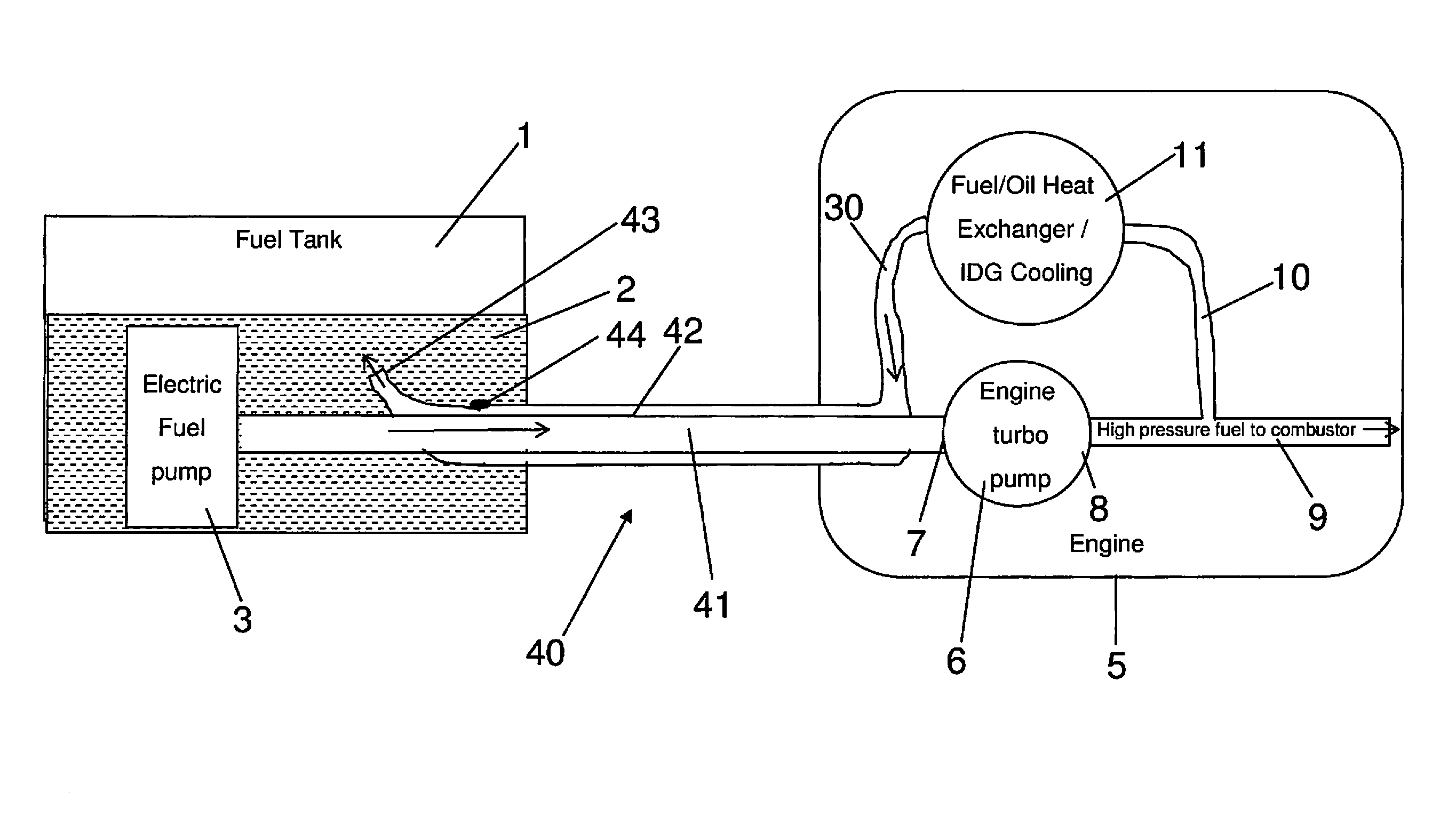
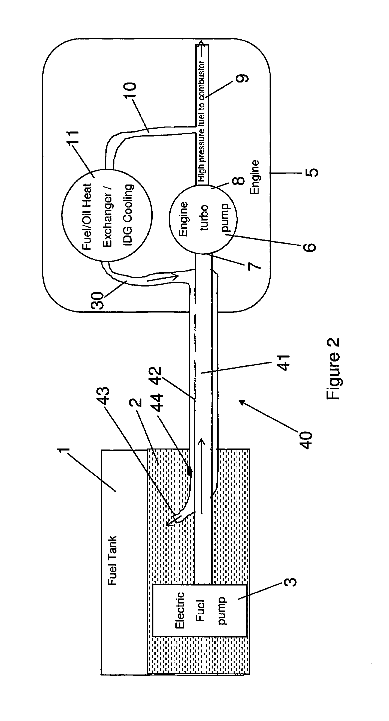
[0029]Turning now to FIG. 2 is shown a schematic representation of the invention in which like reference numerals have been used to denote like parts of the fuel system shown in FIG. 1. Modified or new components of the aircraft fuel system shown in FIG. 2 will now be described in detail.

[0030]Whilst in FIG. 1 the fuel line 4 includes a conduit configured to carry fuel from the fuel tank 1 towards the engine 5, in FIG. 2 the fuel system includes a fuel line 40 comprising a first conduit 41 configured to carry fuel from the fuel tank 1 towards the engine 5 and a second conduit 42 configured to carry fuel from the engine 5 towards the fuel tank 1. The second conduit 42 is disposed annularly around the first conduit 41. The second conduit 42 is fluidly coupled to the outlet of the heat exchanger 11 via a fuel return path 30 within the engine 5. On the fuel tank side, the second conduit 42 has an outlet 43 disposed within the fuel tank 1.

[0031]In operation the “hot” high pressure fuel e...

second embodiment

[0039]the invention will now be described with reference to FIG. 3 in which, once again, like reference numerals have been used to denote like components with FIG. 2. Modified or new components of the aircraft fuel system shown in FIG. 3 will now be described in detail.

[0040]Whilst in FIG. 2 the high pressure fuel in the second conduit 42 exits via outlet 43 directly into the fuel tank 1, in FIG. 3 advantage is taken of the high pressure of the fuel in the second conduit 42 which is used to provide a motive flow for a jet pump 60 within the fuel tank 1.

[0041]As shown in FIG. 3 the second conduit 42 of the fuel line 40 is coupled to a substantially U-shaped pipe 45 so as to reverse the direction of the high pressure fuel flow. The substantially U-shaped pipe 45 carrying the motive fluid for the jet pump 60 has an opening within a convergent duct such that the pressure energy of the motive flow is converted into kinetic energy in the jet pump 60 which draws in the fuel 2 contained wit...


PUM


Abstract

An aircraft fuel system, comprising: a fuel tank; a fuel line; and an engine; wherein the fuel line includes a first conduit configured to carry fuel from the tank towards the engine, and a second conduit configured to carry fuel from the engine towards the tank, wherein one of the first conduit or the second conduit is disposed annularly around the other of the first conduit or the second conduit. Also, a method of operating the system. The system may be used to suppress ice formation in the first conduit and/or provide leakage detection.

Description

FIELD OF THE INVENTION[0001]The present invention relates to an aircraft fuel system. In particular the invention relates to the suppression of ice formation in a fuel line.BACKGROUND OF THE INVENTION[0002]Due to the low ambient temperatures in which some aircraft are expected to operate, aircraft can suffer from ice accretion in fuel lines. Water is an unavoidable contaminant in fuel and if the fuel temperature drops to around 0 degrees Celsius or below then ice formation can occur. If this ice formation is allowed to reach certain components such as engine fuel filters then blockage of the filter can exceptionally occur. In extreme cases this could cause engine failure (Ref: AAIB Special Bulletin S1 / 2008).SUMMARY OF THE INVENTION[0003]A first aspect of the invention provides an aircraft fuel system, comprising: a fuel tank; a fuel line; and an engine; wherein the fuel line includes a first conduit configured to carry fuel from the tank towards the engine, and a second conduit conf...

Claims


Application Information

Patent Timeline
Patent Type & Authority Applications(United States)
IPC IPC(8): B64D37/02B64D37/32B64D37/34F02C7/22
CPCB64D37/02F02C7/222F05D2260/601B64D37/34F05D2220/323B64D37/32F02M31/16F02M37/0052F02M37/10Y02T10/12
Inventor HASKINS, RICHARDTICHBORNE, FRANKLINLAM, JOSEPH K-W
Owner AIRBUS OPERATIONS LTD
Why Eureka
Try Eureka