Monitoring System for Aircraft Drive Wheel System

Active Publication Date: 2016-06-16
BOREALIS TECH LTD
View PDF31 Cites 5 Cited by
  • Summary
  • Abstract
  • Description
  • Claims
  • Application Information

AI Technical Summary

Benefits of technology

The present invention relates to a monitoring system for an aircraft drive wheel drive system that can operate accurately and without being affected by the harsh environment of the aircraft wheel. The system should provide critical system parameter information to ensure safe and reliable operation of the aircraft.

Problems solved by technology

As air travel has increased over the past decades, airport facilities have become more crowded and congested.
As airline fuel costs and safety concerns and regulations have increased, the airline industry is beginning to acknowledge that continuing to use an aircraft's main engines to move aircraft during ground operations is no longer the best option.
The delays, costs, and other challenges to timely and efficient aircraft pushback from airport terminals associated with the use of tugs and tow vehicles makes this type of aircraft ground movement an unattractive alternative to the use of an aircraft's main engines to move an aircraft on the ground.
Not only does such engine use consume fuel, it is also burns fuel inefficiently and produces engine exhaust that contains microparticles and other products of incomplete combustion.
Operating aircraft engines, moreover, are noisy, and the associated safety hazards of jet blast and engine ingestion in congested gate and ramp areas are significant concerns that cannot be overlooked.
None of the foregoing patents, however, suggests a monitoring system that could be used with the described motor structures or other drive means to ensure efficient, reliable aircraft ground movement without reliance on an aircraft's engines.

Method used


Image

  • Monitoring System for Aircraft Drive Wheel System
  • Monitoring System for Aircraft Drive Wheel System
  • Monitoring System for Aircraft Drive Wheel System

Examples


Embodiment Construction

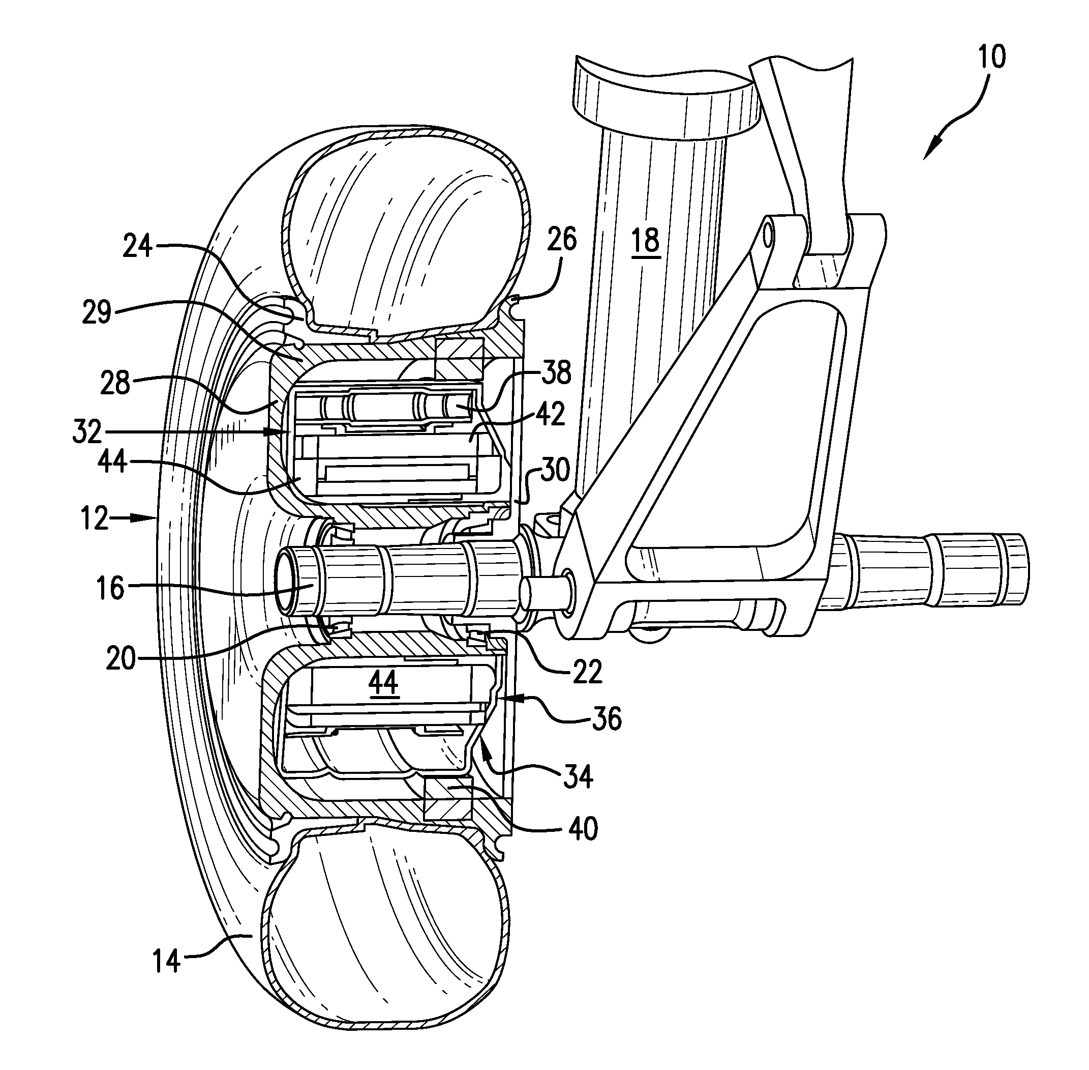
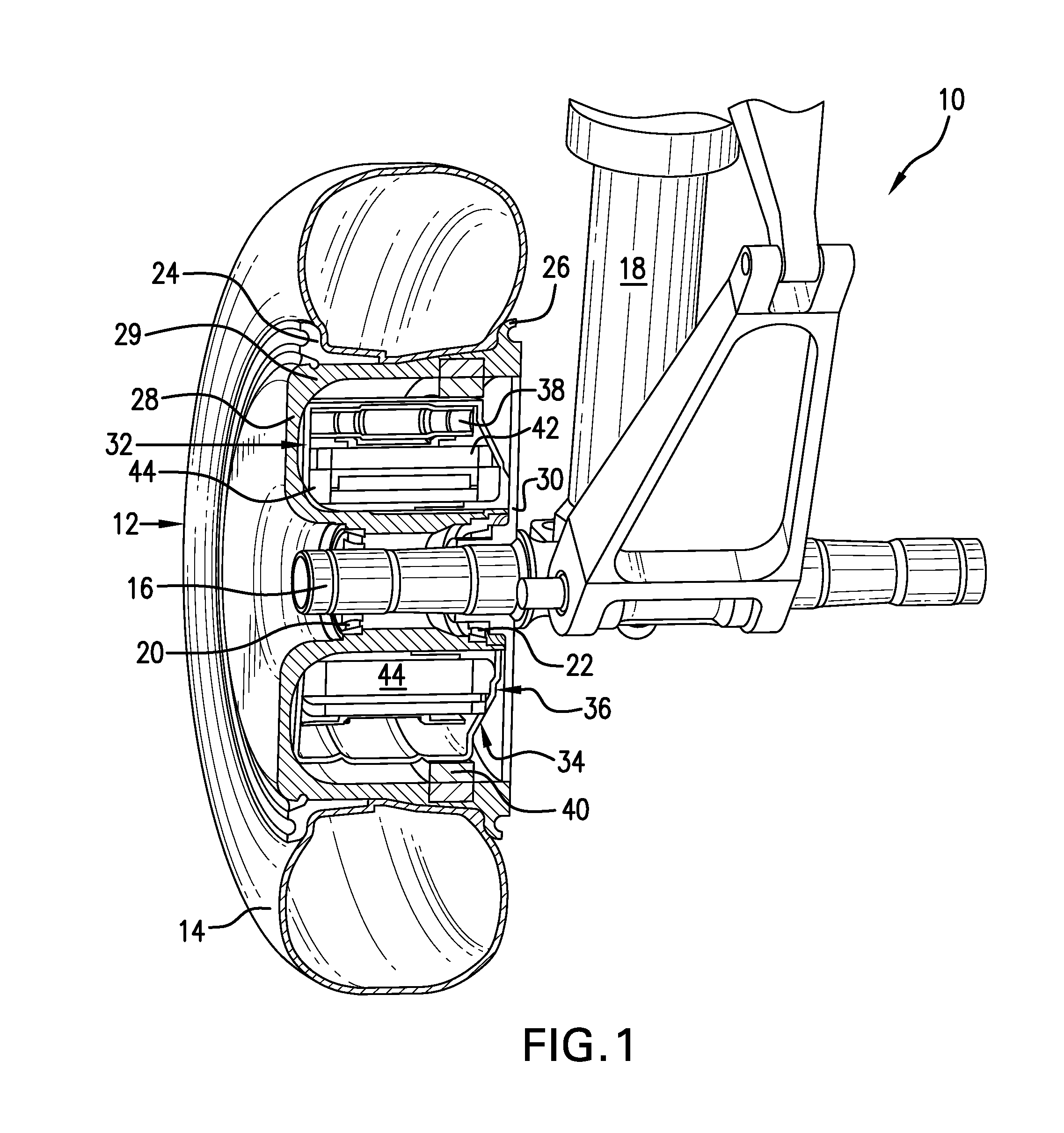
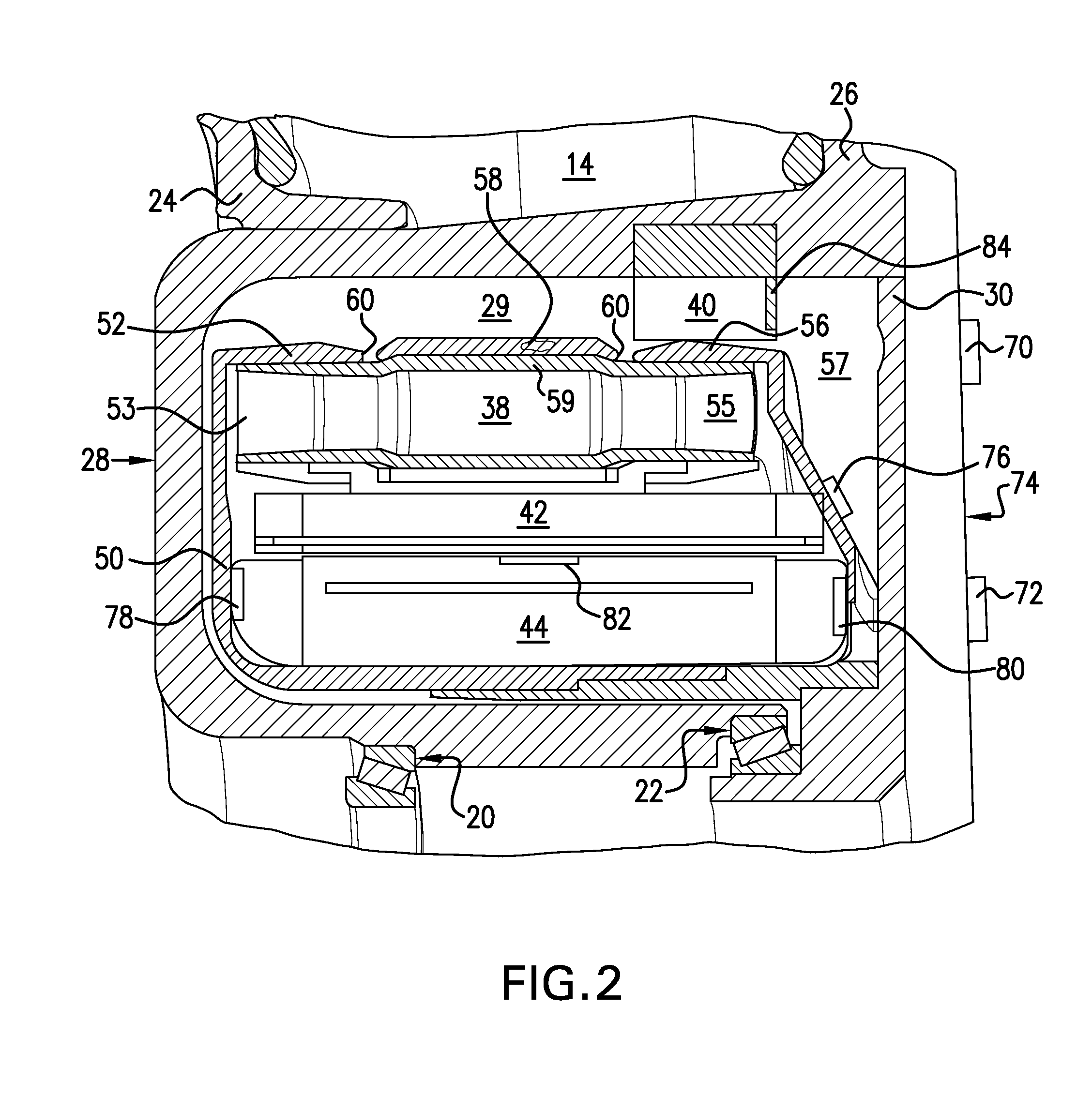
[0019]The benefits of being able to efficiently and safely move an aircraft during ground operations autonomously and without reliance on the aircraft's main engines or external vehicles have long been recognized. Actually achieving these benefits, however, has proved challenging. Applicant's previously proposed aircraft wheel drive means have been demonstrated to effectively power drive wheels and move aircraft on the ground and, thus, can enable aircraft operators to achieve the advantages of autonomous ground movement. The present invention improves the capabilities of Applicant's original aircraft drive wheel drive system and expands the advantages possible when aircraft can be driven during ground operations by controllable onboard drive means independently of the aircraft's main engines and external ground vehicles. These advantages and improvements are achieved, in large part, by the design of an aircraft drive wheel drive system, which incorporates an actuating drive system,...


PUM


Abstract

A monitoring system is provided to ensure continued efficient reliable operation of an aircraft drive wheel drive system, preferably an aircraft drive wheel drive system driven by actuating drive system-actuated drive means, designed to drive an aircraft autonomously during ground operations. The monitoring system includes an array of sensor elements capable of obtaining desired information relating to selected drive system operating parameters and performance indicators during aircraft ground operations. The sensor elements are designed to be functionally located externally of drive system components to obtain information during aircraft ground movement under a range of operating conditions. The operating parameters and / or performance indicators to be monitored preferably include at least drive wheel speed and direction, drive means speed, drive means temperature, and drive means clutch engagement. It is contemplated that the monitoring system could be expanded to include sensors for additional drive system parameters and / or performance indicators.

Description

TECHNICAL FIELD[0001]The present invention relates generally to aircraft drive wheels with drive means capable of moving an aircraft on the ground independently of the aircraft engines or external vehicles and specifically to a monitoring system for an aircraft drive wheel system with a drive means actuatable to move an aircraft autonomously during ground travel without reliance on aircraft main engines or external vehicles.BACKGROUND OF THE INVENTION[0002]As air travel has increased over the past decades, airport facilities have become more crowded and congested. Minimizing the time between the arrival of an aircraft and its departure to maintain an airline's flight schedule, and also to make a gate or parking location available without delay to an incoming aircraft, has become a high priority in the management of airport ground operations. The safe and efficient ground movement of a large number of aircraft simultaneously into and out of ramp and gates areas has become increasingl...

Claims


Application Information

Patent Timeline
IPC IPC(8): B64D45/00B64C25/40B64C25/34
CPCB64D45/00B64D2205/00B64C25/405B64C25/34Y02T50/80G05D1/0083G08G5/065
Inventor COOKMAN, DUWAYNE R.PERKINS, SCOTTCOX, ISAIAH W.
Owner BOREALIS TECH LTD
Why Eureka
Try Eureka