Ejector

a technology of ejector and nozzle, which is applied in the direction of machines/engines, subcoolers, lighting and heating apparatus, etc., can solve the problems of insufficient pressurization of refrigerant in the diffuser portion, inability to achieve improvement effect of nozzle efficiency, and large deviation, so as to achieve sufficient improvement of nozzle efficiency and suppress large deviation

Inactive Publication Date: 2016-06-16
DENSO CORP
View PDF0 Cites 11 Cited by
  • Summary
  • Abstract
  • Description
  • Claims
  • Application Information

AI Technical Summary

Benefits of technology

[0023]Accordingly, it is possible to suppress large deviation between the swirl centers of the refrigerants swirling in the swirling space and the center axis of the swirling space, and refrigerants in a state of two-phase separation, in which liquid-phase refrigerants are unevenly distributed on an outer circumferential side and gas-phase refrigerants are unevenly distributed on an inner circumferential side, can flow into the nozzle passages that are formed on the outer circumferential side of the passage-forming member.
[0024]As a result, boiling of the refrigerants in the state of two-phase separation can be promoted in the nozzle passages, and energy conversion efficiency (corresponding to nozzle efficiency) when pressure energy of refrigerants is converted into kinetic energy in the nozzle passages can be improved. That is, according to the first aspect, in the ejector that depressurizes the refrigerants swirling in the swirling space, nozzle efficiency can be sufficiently improved.

Problems solved by technology

For example, in the ejector of PTL 1, a thermal load of the ejector type refrigeration cycle decreases, and when a pressure difference (a difference between a high pressure and a low pressure) between the pressure of a high-pressure side refrigerant and the pressure of a low-pressure side refrigerant of the cycle decreases, depressurization corresponding to the difference between the high pressure and the low pressure is generated in the first nozzle, and thereby causes the possibility that most of the refrigerant may not be depressurized in the second nozzle.
In this case, since a gas-liquid two phase refrigerant flows into the second nozzle, improvement effects of the nozzle efficiency cannot be obtained, and the refrigerant may not be sufficiently pressurized in the diffuser portion.
However, when the diffuser portion is applied, the length in the axial direction of the nozzle portion in the entire ejector increases, and thereby causes the possibility that a volume of the ejector may unnecessarily increase during a general load of the ejector type refrigeration cycle.

Method used


Image

  • Ejector
  • Ejector
  • Ejector

Examples


first embodiment

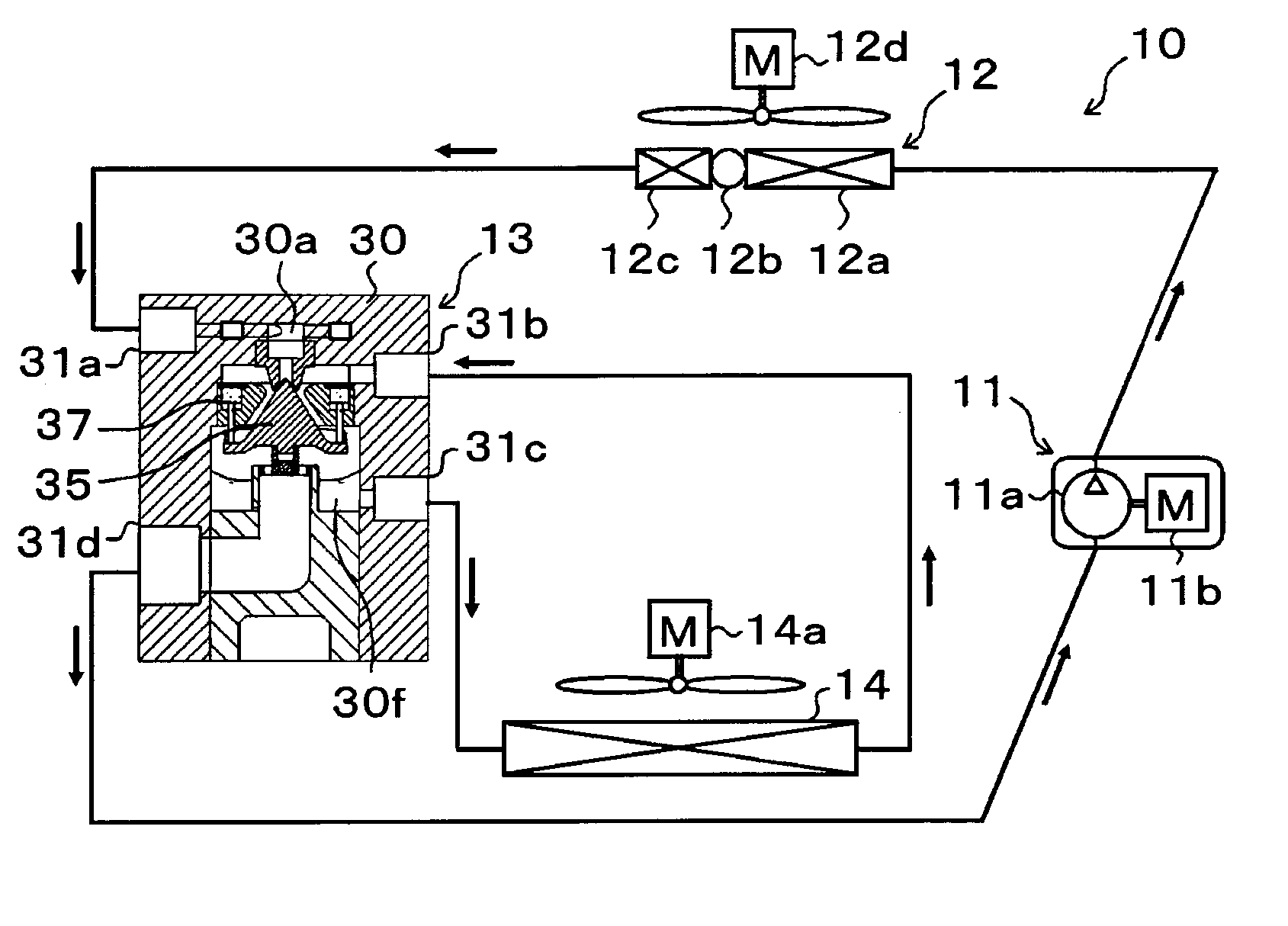
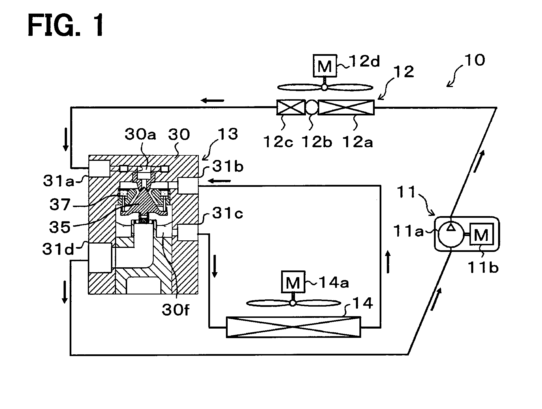
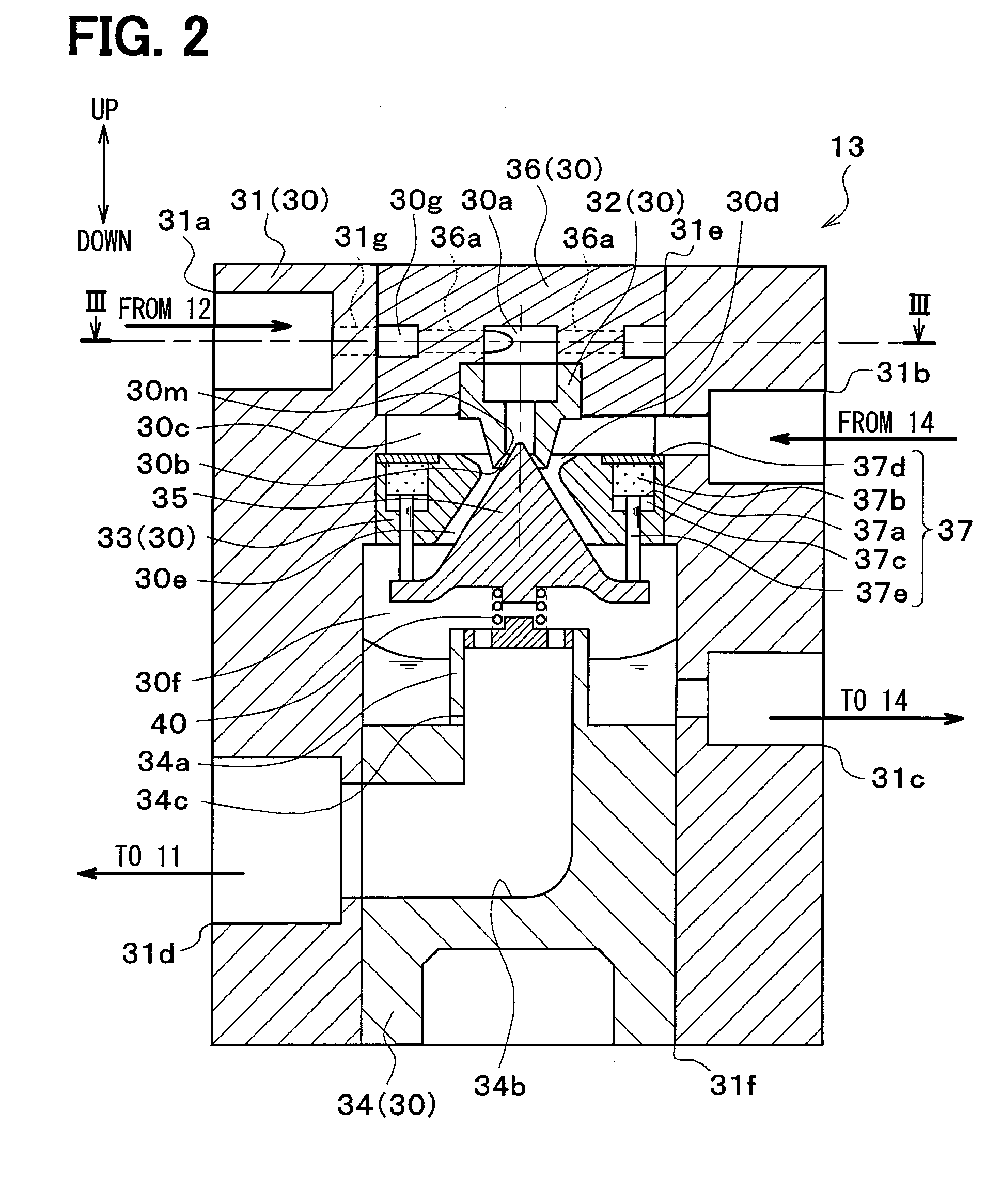
[0058]A first embodiment of the present disclosure will be described with reference to FIGS. 1 to 5. As shown in FIG. 1, an ejector 13 of this embodiment is applied to a vapor compression refrigeration cycle device including an ejector as a refrigerant depressurization device, that is, an ejector type refrigeration cycle 10. The ejector type refrigeration cycle 10 is applied to a vehicle air conditioning apparatus, and has a function which cools blast air blown into a vehicle interior which is a space to be air-conditioned.

[0059]In the ejector type refrigeration cycle 10, an HFC based refrigerant (specifically, R134a) is adopted as a refrigerant, and a subcritical refrigeration cycle in which a high pressure-side refrigerant pressure does not exceed a critical pressure of the refrigerant. Of course, an HFO based refrigerant (specifically, R1234yf) or the like may be adopted as a refrigerant. Refrigerator oil for lubricating a compressor 11 is mixed with the refrigerant, and a portio...

second embodiment

[0149]As shown in FIG. 6, in this embodiment, an example in which configurations of the distribution space 30g and the driving passage 36a of the ejector 13 are changed with respect to the first embodiment will be described. Specifically, in the ejector 13 of this embodiment, a disk-shaped cover plate 36b is fixed to the upper surface of the housing body 31 by press fitting or the like.

[0150]As shown in FIGS. 6 and 7, multiple groove portions that are recessed downward are provided on a portion of an upper surface of the housing body 31 to which the cover plate 36b is fixed. The cover plate 36b is fixed to the upper surface of the housing body 31 by press fitting, the groove portions are partitioned, and the distribution space 30g and the multiple driving passages 36a similar to the first embodiment are provided.

[0151]The nozzle body 32 is fixed to the lower side of the housing body 31 inside the housing body 31 by press fitting or the like. Other configurations are similar to those...


PUM


Abstract

An approximately conical passage-forming member is disposed inside a body in which a swirling space for swirling a refrigerant is formed, and an ejector defines therein a nozzle passage that functions as a nozzle for depressurizing a refrigerant that has flowed out from the swirling space between an inner circumferential surface of the body and the passage-forming member, and a diffuser passage that pressurizes a mixed refrigerant obtained from a refrigerant sprayed from the nozzle passage and a refrigerant drawn from a suction-passage. A plurality of driving passages through which a refrigerant is introduced from a distribution space to the swirling space are formed in the body. In this case, the driving passages are formed in a manner such that a refrigerant flowing in from each driving passage into the swirling space flows along an outer circumference of the swirling space and flows in directions different from each other. Accordingly, nozzle efficiency is sufficiently improved.

Description

CROSS-REFERENCE TO RELATED APPLICATION[0001]The present application is based on Japanese patent application No. 2013-165981 filed on Aug. 9, 2013, the content of which is incorporated herein by reference.TECHNICAL FIELD[0002]The present disclosure relates to an ejector that depressurizes a fluid and draws a fluid by the suction force of a sprayed fluid sprayed at a high speed.BACKGROUND ART[0003]In the related art, as a depressurization device that is applied to a vapor compression refrigeration cycle device, an ejector has been known. In this kind of ejector, a nozzle portion that depressurizes a refrigerant is provided, a gas-phase refrigerant that has flowed out from an evaporator is drawn by suction of a refrigerant sprayed from the nozzle portion, and the sprayed refrigerant and the drawn refrigerant are mixed so as to be pressurized by a pressure increase part (diffuser portion).[0004]Accordingly, in a refrigeration cycle device (hereinafter, referred to as an ejector type ref...

Claims


Application Information

Patent Timeline
Patent Type & Authority Applications(United States)
IPC IPC(8): F25B41/00F25B9/08
CPCF25B9/08F25B41/00F04F5/04F04F5/54F25B40/02F25B2341/0012B60H2001/3298
Inventor NAKASHIMA, RYOTAYAMADA, ETSUHISANISHIJIMA, HARUYUKITAKANO, YOSHIAKI
Owner DENSO CORP
Why Eureka
Try Eureka